Installation Sheet No. 1771ZE R5.0
ZP755B-2 Addressable Sensor Base Sounder
Page
4
501-1771ZE-1
www.gesecurity.eu
•
Copyright © 2007 GE Security B.V. All rights reserved
9 October 2007
Volume setting
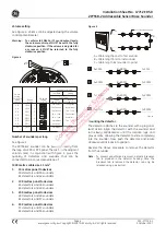
Figure 5
A=10m
A=100m
A=200m
A=300m
B=980m
B=800m
B=600m
B=400m
C=10m
C=100m
C=200m
C=300m
1.
4.
A = Cable length panel to first sounder
B = Cable length first to last sounder
C = Cable length last sounder to panel
A
C
B
DETECTORS & SOUNDERS
2.
3.
3220-01
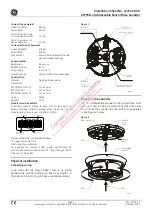
See Figure 4. Volume can be adjusted using the volume
control potentiometer.
Warning: To conform to EN54 Part 3 sound output levels,
the volume control pot MUST be set to the fully
clockwise position. If the volume is adjusted for
any reason, it MUST be returned to the fully
clockwise position.
Figure 4
1
2
3
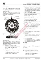
TONE
SELECT
3337-01
Tone A
primary/alert
Tone B
secondary/evac
ZP755
ZP755
ZP755
ZP755
ZP755
ZP755
ZP755
ZP754
Device
mode
DIP Switch
setting
(1) (2) (3)
Intermittent
Continuous
Continuous
Two - Tone
Two - Tone
Intermittent
Not Used
Intermittent
Continuous
Intermittent
Two - Tone
Continuous
Intermittent
Two - Tone
Continuous
0
1
2
3
4
5
6
7
Tone Type
Switch
setting
for device
mode
Switch 6
OFF
OFF
OFF
OFF
OFF
OFF
OFF
ON
Steady
Fast flash
Mapping input type
ON
OFF
Mounting the detector
The detector attaches to the sounder with a plug-and-
twist action. Align the detector with the sounder and
turn slowly anticlockwise until the location lugs and
groves mate, allowing the detector to slide completely
into the sounder. Now push the detector and rotate
clockwise until it locks into position.
Number of sounders per loop
See Figure 5.
The ZP755B-2 sounder can be powered directly from
the loop of a ZP5 or ZP3 panel. The table in the adjacent
column, read in conjunction with figure 5, gives the
quantity of detectors and sounders that can be
connected to a 2-core screened loop of:
Reverse the above procedure to remove the detector
from the sounder.
Note:
To prevent unauthorised removal, a plastic breakout
tab is provided in the detector housing. Once the
breakout tab is removed the detector can only be
released using a picker tool.
1000 metres cable size 1.5 mm
2
1.
10 metres panel to devices
50 detectors and 50 sounders
63 detectors and 42 sounders
2.
100 metres panel to devices
45 detectors and 45 sounders
63 detectors and 40 sounders
3.
200 metres panel to devices
40 detectors and 40 sounders
63 detectors and 37 sounders
4.
300 metres panel to devices
37 detectors and 37 sounders
63 detectors and 35 sounders


