Installation Sheet No. 1771ZE R5.0
ZP755B-2 Addressable Sensor Base Sounder
Current (line powered)
Quiescent (RMS):
820 µA
Alarm (RMS):
4.5 mA
Alarm (maximum. avg.
- excl. device address):
7.5 mA
Alarm (maximum – at
device address):
23 mA
Current (externally powered)
Quiescent (RMS):
470 µA
Alarm (RMS):
500 µA
Max number:
60 per 1 km loop (subject to cable
size and sounder spacing)
Environmental
Application: Indoor
use
EN60529 rating:
IP21C
Temp range:
-10 to 70 °C
Humidity range:
10% to 95% RH (non-condensing)
Construction
Material: Moulded thermoplastic
Dimensions:
ZP710/ZP730 (
∅
x D)
127 x 90 mm
ZP720 (
∅
x D)
127 x 90 mm
ZP732/ZX732 (
∅
x D)
127 x 97 mm
Colour: White
Weight: 150
g
Manufacturer traceability
A barcode label is affixed to each product (see example
below). This label reflects, amongst other things, the date of
manufacture of the product in the form YYDDD.
GN: XXXXXX. XXX YYDDD
JJJJJXXXXX
Job No/Serial No
Bar code Auto human
readable on
Part Number
Date
These numbers are interpreted as follows:
YY = year of manufacture
DDD = day of manufacture
For example the numbers 07134 would indicate that the
product was manufactured on the 134
th
day of the year 2007,
which is 14
th
May 2007.
Physical installation
Connecting wiring
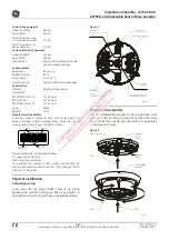
Loop wiring for the plug-in base. There is no wiring
between the sounder and plug-in base. See Figure 1 in
the adjacent column. Plug-in base supplied separately.
Figure 1
LOOP IN (-)
LOOP IN (+)
LOOP OUT (-)
LOOP OUT (+)
EXT GROUND IN (-)
EXT GROUND OUT (-)
EXT 24 VDC IN (+)
EXT 24 VDC OUT (+)
SCREEN
3496-01
Mounting the sounder
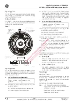
Align the addressable sounder to the plug-in base. Push
up (step 1) and turn the sounder until it clicks into place
(step 2). Push the sounder up once more to engage (step
3). See Figure 2 below.
Figure 2
PLUG-IN BASE
STEP 1
STEP 2
RELEASE/
LOCK
CATCH
3367-01
ADDRESSABLE
SOUNDER
RELEASE
AID x3
STEP 3
Page
2
501-1771ZE-1
www.gesecurity.eu
•
Copyright © 2007 GE Security B.V. All rights reserved
9 October 2007


