11
ATTACHING THE FAN BLADES
INSTALLING THE LIGHT KIT
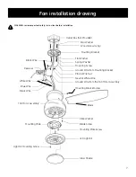
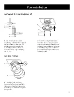
Insert the blade (P) through the slot in the
bottom band, align the holes in the blade
(P) and the bracket, secure with the blade
screws (F) and fibre washers (G) provided.
Repeat this procedure with the other
blades (P).
Remove the 1 of 3 mounting plate screws
(W) from the bottom of motor assembly
(R) and keep it for future use. Loosen the
other 2 screws (do not remove). Place
the key holes on the mounting plate (S)
over the 2 mounting plate screws (W)
previously loosened, turn the mounting
plate (S) until it locks in place at the
narrow section of the key holes. Secure
by tightening the 2 screws previously
loosened and the one previously removed.
Remove the 1 of 3 light kit mounting
screws (X) from the mounting plate (S)
and keep it for future use. Loosen the
other 2 screws (do not remove). While
holding the LED light kit (T) under the fan
motor assembly, make the 2-pin wire
connections: -Red to red and black to
black. Place the key holes on the LED light
kit (T) over the 2 light kit mounting screws
(X) previously loosened, turn the LED light
kit (T) until it locks in place at the narrow
section of key holes. Secure by tightening
the 2 screws previously loosened and the
one previously removed.
Raise glass shade (U) up against the light
kit (T) and secure it to fan by twisting glass
(U) clockwise until snug. Do not over-
tighten.
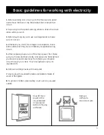
NOTE: before starting installation,
disconnect the power by turning
off the circuit breaker or removing
the fuse at fuse box. Turning power
off using the fan switch may not be
sufficient to prevent electric shock.
F
P
G
W
S
S
X
T
T
U
Fan installation


