background image

FOR 5200 AND 5500 SERIES MODELS ONLY

1.

Remove the room cabinet by pulling it out at the bottom 
to release it (1); then lift it up to clear the rail along the
unit top (2).

2.

Insert the plug into the socket located in the wiring
compartment, making sure the plug is firmly seated
and the latches secure the connector assembly.

3.

Position the cord and install the strain relief and screw
as shown.

4.

Reinstall the room cabinet front by positioning on the
top brackets and securing the sides to the unit.

5.

Install the attachment plug cap into the wall
receptacle and check the Zoneline operation.

2

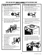
FOR 230/208 VOLT POWER CORD CONNECTIONS ONLY

FOR 7500 SERIES MODELS ONLY

1.

Remove the front panel by removing the filter, taking
out the four front screws, the upper two screws from
the top of the panel, and the shipping screws on each
side, if present. (Discard the two side shipping screws,
if present.)

2.

Remove the junction box cover and the junction box
and discard.

3.

Connect the power cord, with a loop, through the
strain relief.

4.

Replace the case front panel by replacing the four
front screws and the two top screws. Replace the
filter.

Strain relief

IMPORTANT:

Power cord
must have a
loop.

Remove
junction
box and
cover

Side
shipping
screw

Side
shipping
screw

Screw

Plug into
building
receptacle

Yellow plug 
to chassis
connector

Strain
relief

Cord

Содержание RAK3152

Страница 1: ...r Note to Consumer Keep these instructions with your Owner s Manual for future reference TOOLS NEEDED 1 4 Nut driver Phillips screwdriver Wire cutter For direct connect applications only This kit is for use with 230 208 volt 5200 5500 and 7500 Series GE Zoneline units only IMPORTANT NOTES This unit must be properly grounded The electrical rating marked on the previously installed Zoneline and powe...

Страница 2: ...e Zoneline operation 2 FOR 230 208 VOLT POWER CORD CONNECTIONS ONLY FOR 7500 SERIES MODELS ONLY 1 Remove the front panel by removing the filter taking out the four front screws the upper two screws from the top of the panel and the shipping screws on each side if present Discard the two side shipping screws if present 2 Remove the junction box cover and the junction box and discard 3 Connect the p...

Страница 3: ...are engaged 10 Dress the wiring inside the junction box and attach the cover plate with screws A and C 11 Reinstall the room cabinet front FOR 230 208 VOLT DIRECT CONNECT APPLICATIONS ONLY 3 3 4 3 Connector 6 Conduit 9 pin connector Unit 9 pin receptacle C A C A B C A C A FOR 7500 SERIES MODELS ONLY 1 Measure 7 down the cord from where it emerges from the back of the yellow 9 pin connector and cut...

Страница 4: ... with some color other than green or white Connect the green lead of the power supply kit to the power supply and branch circuit ground 3 Phase 208 VAC with Crazy Leg When connecting the Zoneline to a three phase circuit with Crazy Leg for 208V applications Connect the white and black leads of the Zoneline power supply kit to the branch circuit Neutral and L1 leads The white lead of the power supp...

Отзывы: