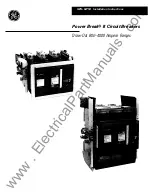


Power Break®
II
Circuit Breakers
Draw-Out Breaker Installation
Draw-Out
Position
Indicator
Position
Switch
Rejection
Feature
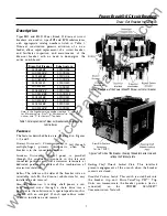
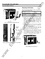
Figure
J
Right side of the breaker, showing the rejection feature,
draw-out position switch draw-out position indicator, and electric
operator cutoff switch.
Draw-Out Position Indicator.
Indicates whether the
breaker is in the connected, test, or disconnect posi
tion.
Electric Operator Cutoff Switch.
Prevents cycling of the
spring-charging motor during installation or removal
of a breaker.
Draw-Out Interlock.
This feature trips a closed circuit
breaker if the wrench
interlock is deliberately
defeated. The breaker is tripped before the primary
disconnects part as the breaker is racked out and
before the primary disconnects engage as the breaker
is racked in.
Rejection Feature.
This feature prevents insertion of a
breaker into a substructure of lower ampere rating or
higher short-circuit rating. It does not reject a
breaker with incompatible control wiring. See the
label on the breaker or Table
I
for the proper sub
structure catalog number. (Also shown in Figure 8.)
Table 2 illustrates the rejection scheme logic. Note that
breakers
may be safely used in
higher-rated
substructures. However, local and industry codes and
standards require that conductors be sized to the
substructure.
Therefore,
installing
breakers
i n
substructures with higher ratings is possible, but not
economical.
2
SSD08202, X204, X208
SHD08X202, X204,
SPHDOS08
SSD16X210, X216
SPSDOS16
SHD16X210, X216
SPHDOS16
SSD20X220
SPSDOS20
SH D20X220
SPH DOS20
SSD25X21 0, X220, X325
SPSDOS25
SH D25X21 0, X220, X325
SPH DOS25
SSD30X330
SPSDOS30
SPHDOS30
SSD40X440
SPSDOS40
SH D40X440
SPH DOS40
Note: In the breaker catalog number, replace
"
X
"
with "B" for
MicroVersaTrip PlusTM or MicroVersaTrip P MTM Trip Units or with
"D" for Power+TM Trip Units
Table
2
Illustration of the rejection-scheme logic, showing which
breakers may be installed in which substructures.
Draw-Out Padlock Accessory.
When
a padlock i s
installed, this feature works with the racking shaft
lockout plate to prevent engagement of the racking
shaft wrench.
Shutter Actuator.
A stud actuates the optional shutter
accessory.
By-Pass Switch Actuator.
Operates the optional by-pass
switch accessory.
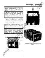
Lifting Bar.
The Lifting Bar, catalog number TDOLB, i s
available for safe handling of the draw-out breaker, as
illustrated in Figures
4
and
5.
Installing the Breaker
Use the following procedure to install the draw-out
breaker into the substructure.
1.
Attach the Lifting Bar, catalog number TDOLB,
by locating the hooks on the bar beneath the
shoulder studs of the breaker, as illustrated i n
Figures
4
and
5.
2.
Pull out the substructure rails until they drop into
the horizontal locked position. Lower the breaker
so that the grooves in the rollers drop over the
rails.
3.
Make sure the grooves in all rollers straddle the
rails, as illustrated in Figure 6, then remove the
Lifting Bar and push the breaker into the
substructure until it stops in the
DISCONNECTED
position. Then lift the rails and push them in to
the stored position.
www
. ElectricalPartManuals
. com


