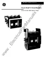

Power Break®
II
Circuit Breakers
Draw-Out Breaker Installation
Table of Contents
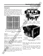
Description
......................................... . ....................................... . . . . . . . . . ............. . . . . ...................
1
Features
....... ......... . . .. .............
.
..... . . . ............... .......... . . ............ . . ................
.
....................
1
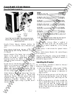
Installing the Breaker
..
.
........ . . . ..... . . .
.
...... . . . . ... . . .. . . ......... . . . . ....... . . . ............
.
...............................
2
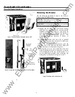
Removing the Breaker.
............................................................. . ........ ..................... . . . . . . ...........
4
Maintenance Procedures
. . . . . . . . . . . . . . . . . . ............ ........... ............ ...... ........................... . ...................
5
Lubrication
. . . . . . . . . . . . . ................ . . . . . . . .................................... .......................................................
6
List of Figures
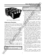
1.
Rear view of the Power Break® II draw-out circuit breaker
... . . . . . . . . .. . . . . . . . . . . . . . . . . . . . .. . . . . . . . . . . . . . . . . . . . . 1
2.
Left side of breaker, showing padlock accessory and racking shaft lockout plate
. . . . . . . . . . . . . . . .. . . . .. . . 1
3. Right side of the breaker, showing the rejection feature, drawout position switch, drawout
position indicator, and electric operator cutoff switch . . . . . . . . . . . . . . . . . . . . . . . . . . . . . . . . . . . . . . . . . . . . . . . . . . . . . . . . . . . . . . . 2
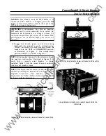
4.
Lifting Bar attached to a draw-out breaker for manual lifting
. .. .................. ..... . . . . . . . . . . . .
.
. . . ........
3
5. Lifting Bar attached to a draw-out breaker for lifting with a hoist
. .. . . . . . ........ . . ....
.
. . . . . . . . . . .
.
.
.
. . . . . .
3
6. Breaker installed on rails, ready to be pushed into the substructure
. . . . .......... . . .
.
. . ...............
.
. . ....
3
7.
Wrench attached to the breaker racking shaft.
..
.
. . . . . . . . . . ...... ..... . . . . . .. . . . ....... . . . ........ . . . . . ...... . . . . . . . . .
4
8.
Compartment position indicator on the front of the breaker
........ . .
.
..
. .
..
.
..... . . . . . .....
.
. . . . .. . . .
.
. . .
.
.
. . .
4
9.
Withdrawing the substructure rails
. . ...........
.
. . . . . . . ..... . . .. . . . .. . ... . . . . . .................. . . . . . . . . .
.
....... . . . . . . . . .
. 4
10. Rotating the breaker forward for inspection . . . . . . . . . . .. .. .. . . . . . . . . . . . . . . . . . . . . . . .. . . . .. . . . . . . . . . . . .. . . . . . . . . . .. . . . . .. . 5
List of Tables
1.
Catalog numbers of draw-out breakers and corresponding substructures . . . . . . . . . . . . . . . . . . . . . . . . . . . . . . . . . . . 1
2. Illustration of the rejection-scheme logic, showing which breakers may be installed i n
which substructures
.
.
.
. . . .
.
. . ....... . . . . . . .
.
. . . . . . . . . . . . . . . . . . . . .
.
. . . . . . . . . . . . . .
.
. . . .
.
. . . . . ..
.
.
. . . .
.
. . . . . . . . . . . . . . . . . .
.
. . . . . . . . . ..
.
.
.
2
www
. ElectricalPartManuals
. com


