20
49-80516-4
INST
ALL
ATION INSTRUCTIONS
Installation Instructions
CABINET PREPARATION
1
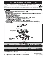
PREPARING FOR INSTALLATION
Positioning the cooktop
The cooktop is designed to look best when centered in a
cabinet at least 30" wide.
The exhaust vent beneath the cooktop must be located
between wall studs or floor joists so that the ductwork may
be installed properly.
The downdraft system with blower, motor and ductwork will
occupy the cabinet below the cooktop. Drawers cannot be
installed below this cooktop.
Avoid placing cabinets above the cooktop unit, if possible,
in order to reduce the hazards caused by reaching over
heated surface units.
If the cabinetry is used above the cooktop, allow a minimum
30" clearance between the cooking surface and the bottom
of the unprotected cabinet.
If the clearance between the cooktop and the cabinetry is
less than 30", the cabinet bottom must be protected with
a flame retardant millboard at least
1
/
4
" thick, or gypsum
board at least
3
/
16
" thick, covered with 28 gauge sheet steel
or 0.020" thick copper. Clearance between the cooktop and
the protected cabinetry
MUST NEVER BE LESS THAN 24".
EXCEPTION:
Installation of a listed microwave oven or
cooking appliance over the cooktop shall conform to the
installation instructions packed with that appliance.
Working areas adjacent to the cooktop should have an
18" minimum clearance between the countertop and the
bottom of the cabinet. If the clearance is less than 18”, the
adjacent cabinets should be at least 5” from the side edge
of the cooktop.
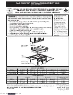
2
PREPARING THE BASE CABINET
This cooktop is designed to fit easily into a variety of
cabinets. However, the combined installation of a downdraft
vent and a cooktop require careful consideration.
Some cabinets may require modifications.
This installation requires a 24” min. deep cabinet base.
The cabinet must be at least 30” wide.
Preparing a cabinet that is against a wall
In some cabinets, the sides may need to be scooped or cut
down 5
3
ø
4
” as shown, and the corner braces removed in
order to accommodate the unit.
In 75 cm and 90 cm frameless European cabinets,
the back panel may need to be cut down 5
3
ø
4
” to
accommodate the unit.
Preparing a peninsula or island-type cabinet
In a peninsula or island type cabinet, the sides may need to
be scooped or cut down, and the corner braces removed in
order to accommodate the unit
.
13" max.
depth of
unprotected
overhead
cabinets
5" min. clearance
from cutout to
side walls
30" min. clearance
from countertop
to unprotected
overhead surface
18" min. height
from countertop to
nearest cabinet on
either side of the unit
5
3
ø
4
”
Approx.
5
3
ø
4
”
Approx.
for European
cabinets
Содержание PGP9830DRBB
Страница 32: ...32 49 80516 4 Notes...
Страница 33: ...49 80516 4 33 Notes...
Страница 34: ...34 49 80516 4 Notes...
Страница 68: ...32 49 80516 4 Notas...
Страница 69: ...49 80516 4 33 Notas...
Страница 70: ...34 49 80516 4 Notas...