Chapter 1. Introduction
22
PACSystems* RX3i & RSTi-EP PROFINET IO-Controller User Manual
GFK-2571N
1.6.7
Two RX3i CPUs with Two PROFINET Networks and One Ethernet
Network
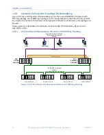
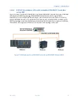
Figure 12 shows two RX3i CPU nodes, each with one RX3i PROFINET Controller module and one RX3i Ethernet
Transmitter Module (ETM). The PROFINET Controller modules are connected to separate networks (IO LAN1
and IO LAN2 in the illustration). IO LAN1 and IO LAN2 are used for PROFINET IO traffic.
The RX3i Ethernet Transmitter Modules are connected to the same Ethernet LAN (LAN3 in the illustration).
Proficy Machine Edition (PME), HMI, and Historian use LAN3 to configure and monitor the application. LAN3 is
also used for inter-node communication such as EGD, SRTP, and Modbus/TCP. The three separate networks do
not compete for network bandwidth or interfere with one another.
IO-Device 1
IO-Device 2
IO-Device 2
IO-Device 1
RX3i Controller CPU Node
with one PROFINET
Controller and one ETM
IO LAN 1
IO LAN 2
IO-Device 3
Prog/Config
Connection
LAN 3
EGD/SRTP/ModbusTCP/etc.
Programmer
(PME)
Proficy HMI
Historian
NOTE:
RX3i Controller CPU Node
with one PROFINET
Controller and one ETM
Daisy-chain shown for
clarity. A star or ring
topology is preferred.
Figure 12: RX3i System with two PROFINET LANs & one Ethernet LAN


