GEK-98846A
80
6.2.8.4. 3PH FAULTS
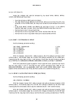
Apply the voltages and currents indicated by the faults 3PH0, 3PH25, 3PH50,
3PH75, and 3PH99 and check that:
−
the relay signals an 3PH fault in all of them.
−
the relay finds the fault distance in all of them with an error of less than 5%. For
example: for the 3PH50 fault, the relay must locate the fault between 45 and 55
km.
−
in the faults 3PHO, 3PH25, and 3PH50, the relay trips in zone 1, in the 3PH75
fault the relay trips in zone 2, and in the 3PH99 fault the relay trips in zone 3.
−
the trip time in zone 1 is less than 50ms.
−
the trip time in zone 2 is greater than 100 ms and less than 150 ms.
−
the trip time in zone 3 is greater than 2()0 ms and less than 250 ms.
6.2.9 ZONE 1 EXTENSION SCHEME
Set the following protection setting:
209 - PROT. IN SERVICE
1= Z1X
223 - Z1 REACH:
4.50
224 - Z1X REACH:
1.20
225 - Z2 REACH:
6.00
226 - Z3 REACH:
15.0
With the breaker closed (CC1 without power), the Z1X without pull back (CC7
without power), momentarily apply the currents and voltages indicated by the AG99 fault,
checking that the relay trips in zone 1 and recloses. Check that the last events generated
were TRIP IN Z 1X. BREAKER OPENED, BREAKER CLOSED, and FAULT CLEARED.
With Z1X pulled back (power applied to CC7) repeat the same operation and check
that the relay trips in zone 2, and that the last events generated were TRIP IN Z2,
BREAKER OPENED, (the event(s)MEAS_UNIT ACT and/or OPEN BRK CURR. may
appear at the same time as one of the previous events or be inserted among them).
6.2.10 ZONE 2 ACCELERATION SCHEME (MLP3000)
Set the following protection setting:
208 - PROTEC. SCHEME:
2=ACZ2
With the breaker closed (CC1 without power) and without channel reception (CC6
without power), momentarily apply the currents and voltages indicated by the AG:0 fault
checking that the transmission start output is activated (the D11-D12 contact closes).
With the breaker closed (CC1 without power) and without channel reception (CC6
without power), momentarily apply the currents and voltages indicated by the AG80 fault
checking that the relay trips and recloses and that the last events generated were TRIP IN
Содержание MLP1000
Страница 94: ...GEK 98846A 93 Figure 1 System diagram with MLP CPR and TTI ...
Страница 95: ...GEK 98846A 94 Figure 2 Case dimensions and drilling form 1 rack ...
Страница 96: ...GEK 98846A 95 Figure 3 1 External Connections MLP1000 ...
Страница 97: ...GEK 98846A 96 Figure 3 2 External Connections MLP1000 ...
Страница 99: ...GEK 98846A 98 Figure 3 4 External Connections MLP1000 ...
Страница 100: ...GEK 98846A 99 Figure 3 5 External Connections MLP2000 ...
Страница 101: ...GEK 98846A 100 Figure 3 6 External Connections MLP2000 ...
Страница 103: ...GEK 98846A 102 Figure 3 8 External Connections MLP2000 ...
Страница 104: ...GEK 98846A 103 Figure 3 9 External Connections MLP3000 ...
Страница 105: ...GEK 98846A 104 Figure 3 10 External Connections MLP3000 ...
Страница 107: ...GEK 98846A 106 Figure 3 12 External Connections MLP3000 ...
Страница 108: ...GEK 98846A 107 Figure 4 Protection Logic ...
Страница 109: ...GEK 98846A 108 Figure 5 1 Trip decision diagram ...
Страница 110: ...GEK 98846A 109 Figure 5 2 Trip decision diagram ...
Страница 111: ...GEK 98846A 110 Figure 5 3 Trip decision diagram ...
Страница 112: ...GEK 98846A 111 Figure 5 4 Trip decision diagram ...
Страница 113: ...GEK 98846A 112 Figure 6 1 Z1X protection scheme ...
Страница 114: ...GEK 98846A 113 Figure6 2 ACCZ2 Protection scheme ...
Страница 115: ...GEK 98846A 114 Figure7 LPU function diagram ...
Страница 116: ...GEK 98846A 115 Figure 8 1 ROD function logic ...
Страница 117: ...GEK 98846A 116 Figure 8 2 ROD function diagram ...
Страница 118: ...GEK 98846A 117 Figure 9 1 DD function logic ...
Страница 119: ...GEK 98846A 118 Figure 9 2 DD function diagram ...
Страница 120: ...GEK 98846A 119 Figure 10 1 FF function logic ...
Страница 121: ...GEK 98846A 120 Figure 10 2 FF function diagram ...
Страница 122: ...GEK 98846A 121 Figure 11 1 Recloser diagram ...
Страница 123: ...GEK 98846A 122 Figure 11 2 Recloser Diagram ...
Страница 124: ...GEK 98846A 123 Figure 11 3 Recloser Diagram ...
Страница 125: ...GEK 98846A 124 Figure 12 Fault selector ...
Страница 126: ...GEK 98846A 125 Figure 13 Menu Tree Diagram ...
Страница 127: ...GEK 98846A 126 Figure 14 MLP3000 Settings and data ...
Страница 128: ...GEK 98846A 127 Figure 15 Connection scheme for relay tests ...
Страница 129: ...GEK 98846A 128 Figure 16 Power swing diagram function ...
Страница 130: ...GEK 98846A 129 Figure 17 Mho Reactance characteristics of the MLP ...


