GEK-98846A
61
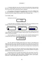
change takes effect immediately. The configuration is stored in the permanent
EEPROM memory.
5.4.12. INTERACTION OF THE KEYBOARD WITH REMOTE COMMUNICATIONS
In the MLP, the keyboard has priority over remote communications. When the
keyboard is active, all messages specifically directed to the unit from a remote controller
are responded to with the error message "RELAY BUSY".
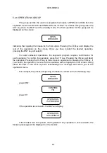
The keyboard becomes active when pressing either the SET, INF, or ACT keys. It is
also activated by pressing the ENT key for simplified operations, or one of the numeric
keys for entry into the configuration unit. If, when pressing one of these keys, remote
communications are active. the following message will be displayed on the monitor:
BREAKING REMOTE
PLEASE WAIT
which remains displayed for the amount of time necessary to break the remote
communications session. To ensure transmission integrity, the MLP is designed so that
remote communications cannot be interrupted if a message is being transmitted.
For this reason, the previous message may remain displayed for a noticeable
amount of time if the transmission rate is low (300 -600 baud) and will be practically
invisible at high transmission rates (above 2400 baud).
When the user establishes serial communications \with the relay, a blinking R" will
appear on the left of the first line on the relay display. This is to notify a local user that any
keypad action will disconnect the remote communications session.
If the unit number or transmission rate parameters are modified, the
communications will be affected as soon as the changes are confirmed. The same occurs
for remote communication authorizations.
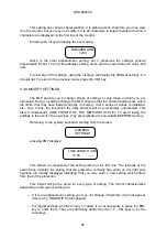
Once the remote communications have been broken, the MLP will operate as
normal. The keyboard will remain active until the operator deactivates it by pressing the
END or CLR keys while the MLP is in standby. The asterisk displayed on this screen
indicates that the keyboard is active and remote communications are inhibited. Upon
deactivating the keyboard the asterisk will disappear:
(*)
MLP
CLT
MLP
GENERAL ELECTRIC
END
GENERAL ELECTRIC
Keyboard active
Keyboard inactive
In any screen in which values are not changed for a period of 5 minutes and 20
seconds, and no keys have been pressed, or approximately 30 minutes in refresh
operations such as the status request or single key operations, the MLP returns to the
standby mode and deactivates the keyboard.
Содержание MLP1000
Страница 94: ...GEK 98846A 93 Figure 1 System diagram with MLP CPR and TTI ...
Страница 95: ...GEK 98846A 94 Figure 2 Case dimensions and drilling form 1 rack ...
Страница 96: ...GEK 98846A 95 Figure 3 1 External Connections MLP1000 ...
Страница 97: ...GEK 98846A 96 Figure 3 2 External Connections MLP1000 ...
Страница 99: ...GEK 98846A 98 Figure 3 4 External Connections MLP1000 ...
Страница 100: ...GEK 98846A 99 Figure 3 5 External Connections MLP2000 ...
Страница 101: ...GEK 98846A 100 Figure 3 6 External Connections MLP2000 ...
Страница 103: ...GEK 98846A 102 Figure 3 8 External Connections MLP2000 ...
Страница 104: ...GEK 98846A 103 Figure 3 9 External Connections MLP3000 ...
Страница 105: ...GEK 98846A 104 Figure 3 10 External Connections MLP3000 ...
Страница 107: ...GEK 98846A 106 Figure 3 12 External Connections MLP3000 ...
Страница 108: ...GEK 98846A 107 Figure 4 Protection Logic ...
Страница 109: ...GEK 98846A 108 Figure 5 1 Trip decision diagram ...
Страница 110: ...GEK 98846A 109 Figure 5 2 Trip decision diagram ...
Страница 111: ...GEK 98846A 110 Figure 5 3 Trip decision diagram ...
Страница 112: ...GEK 98846A 111 Figure 5 4 Trip decision diagram ...
Страница 113: ...GEK 98846A 112 Figure 6 1 Z1X protection scheme ...
Страница 114: ...GEK 98846A 113 Figure6 2 ACCZ2 Protection scheme ...
Страница 115: ...GEK 98846A 114 Figure7 LPU function diagram ...
Страница 116: ...GEK 98846A 115 Figure 8 1 ROD function logic ...
Страница 117: ...GEK 98846A 116 Figure 8 2 ROD function diagram ...
Страница 118: ...GEK 98846A 117 Figure 9 1 DD function logic ...
Страница 119: ...GEK 98846A 118 Figure 9 2 DD function diagram ...
Страница 120: ...GEK 98846A 119 Figure 10 1 FF function logic ...
Страница 121: ...GEK 98846A 120 Figure 10 2 FF function diagram ...
Страница 122: ...GEK 98846A 121 Figure 11 1 Recloser diagram ...
Страница 123: ...GEK 98846A 122 Figure 11 2 Recloser Diagram ...
Страница 124: ...GEK 98846A 123 Figure 11 3 Recloser Diagram ...
Страница 125: ...GEK 98846A 124 Figure 12 Fault selector ...
Страница 126: ...GEK 98846A 125 Figure 13 Menu Tree Diagram ...
Страница 127: ...GEK 98846A 126 Figure 14 MLP3000 Settings and data ...
Страница 128: ...GEK 98846A 127 Figure 15 Connection scheme for relay tests ...
Страница 129: ...GEK 98846A 128 Figure 16 Power swing diagram function ...
Страница 130: ...GEK 98846A 129 Figure 17 Mho Reactance characteristics of the MLP ...


