


05-6398A01, Rev. C
MDS Master Station Setup Guide
3
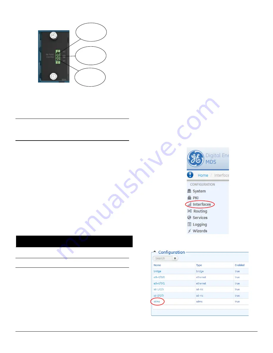
+/- VDC Input
+/- VDC Input
Center Terminal;
Chassis ground
Figure 7: DC Power Connector
5.
Connect a PC for Configuration (LAN or USB port).
This pre-
pares the Master Station for programming of desired operating pa-
rameters. Configuration is further described in Section 3.0
SOFTWARE CONFIGURATION
.
NOTE
If serial-based cabling is used for configuration, an adapter
may be required at the PC, as many PCs do not offer a serial
port. In such cases, a USB-to-Serial adapter (with appropriate
driver software) may be used. These adapters are available
from a number of manufacturers.
6.
Redundant Units
—The Alarm/Relay module includes a manual
override toggle switch, which can be set into one of three positions
to associate it with a particular radio. The toggle switch is locking,
and must be pulled out to change positions. Switch functions are as
follows:
Up
—Radio A;
Down
—Radio B;
Center
—Automatic
When the switch is set to Automatic, the active radio is determined
by radio module presence and alarm status. If only one radio mod-
ule is installed (A or B) it is recommended that the switch be set to A
or B, as appropriate.
7.
Radio, Alarm/Relay, and Duplexer Connections
—The
Alarm/Relay module provides two alarm outputs, one for major and
one for minor alarms. This module also provides TX/RX audio, PTT
(TX keying), and analog RSSI connections. See Section 6.0
ALARM/AUDIO PINOUT
for pin-out connections.
All other required connections on the front of the unit are cabled at
the factory per ordered options.
3.0 SOFTWARE CONFIGURATION
In the following steps, you will log into the unit’s configuration system
and set the basic operating parameters for the unit.
NOTE
Consult your System Administrator if you are unsure
of the proper configuration settings for your network.
3.1
Configuration via Web Device Manager
The configuration PC may be connected to the unit by USB or Ethernet.
The following steps describe a configuration using the GE MDS Device
Manager running on the unit. The Device Manager is accessible through
ETH1 or ETH2 using a web browser.
Minimum browser requirements: IE10 or later, Chrome, Firefox, or
Safari.
1.
Open a web browser and navigate to the IP address of the unit
(default Ethernet IP address is
192.168.1.1
). The initial sign-in
prompt appears.
2.
Enter the username and password (
admin
is the default entry for
both fields). Click
Sign In
. Upon successful login, the
Device Over-
view
page appears.
3.
For general configuration, the
Initial Setup Wizard
will appear and
provide guidance in typical setups. This is disabled after the initial
setup but may be re-run at any time by accessing the
Wizards
link
on the left side of the screen, and clicking
Initial Setup
.
Key items that should be reviewed and/or set for the radio are:
•
Create one-time programmable passwords for unit recovery
•
Change login passwords (to maintain security)
•
Evaluate default factory configuration and lock the unit down to
the required security level
4.
When the Initial Setup wizard completes, select the
SD Configura-
tion Wizard
, which steps you through initial SD Radio Module con-
figuration. Key items that should be reviewed and/or set include:
•
Frequency plan
•
Modem selection
•
Keying mode
•
Serial data interface configuration
•
Encryption settings
5.
For additional SD radio configuration and status options, navigate to
SDMS Configuration
using the following selections:
a.
Select
Interfaces
on the left hand menu.
b.
Click on the
sdms
interface name in the Interfaces
Configura-
tion
table...


