background image

GEK-49849 

I NSTANTANEOUS  OVERCURRENT  UNI T 

The  pickup  of  the  in stantaneou s  overcurrent  unit  can  be  adju sted  over  an 

eight-to- one  r ange,  as  indicated  in  T ab l e   6,  by  varying  the  ten sion  of  the  spiral 

control  spring  and  by  sel ection  of  the  appropriate  series  or  p aral l e l  connections .   The 

outside  end  of  this  spring  is  fastened  to  a  post  on  the  adjusting  ring  above  the  moving 

contact,  an d  the  ring  is  in  turn  c l amped  in  position  by  a  hex agonal -head  l ocking  screw. 

If  this  screw  is  l oosened,  the  ring  can  be  s l ipped  to  vary  the  spring  ten s ion . 

Make  test  connections  as  shown  for  the  app l ic ab l e  rel ay  type  by  Fig .  24 . 

I n  

adju sting  pickup,  the  desired  pick up  current  shou l d   be  pas s sed  through  the  coil s  and 

the  contro l   spring  shou l d   be  adju sted  u ntil  the  contact  ju st  c l oses .  The  adjusting 

ring  shou l d  then  be  l ocked  in  position  and  the  pick up  current  rechecked .  Note  that  the 

directional -unit  contacts  must  be  hel d   c l osed  during  this  adjustment. 

I NSTANTANEOUS  UNIT 

Make  sure  that  the  instantaneous  u nit  is  in  the  c orrect  r ange  in  which  it  is  to 

operate .  See  the  intern a l   connections  diagr am  and  T abl e  7 .   Whenever  possibl e,  use the 

higher  range  since  the  higher  range  has  a  higher  continuous  ratin g .  

The  instantaneous  unit  has  an  adju stab l e  core  l ocated  a t  the  top  of  the  unit.  To 

set the  instantaneous  unit  to  a  desired  pick up,  l oosen  the  l ocknut  and  adju st  the  core. 

Turning  the  c ore  c l ockwise  decreases  the  pick up,  tur ning  the  c ore  counter c l ockwise 

increases  the  pick up .  Bring  up  the  c urrent  s l owly  until  the  u nit  pick s  u p .   It  may  be 

necessary  to  repeat  this  operation,  u ntil  the  desired  pick u p   val ue  is  obtaine d .   Once 

the  desired  pickup  val ue  is  reached,  tighten  the  l ocknut. 

CAUT ION: 

Refer  to  T abl e  7  for  the  contin uous  and  one  second  r atings  of  the 

instantaneous  unit.  Do  not  exceed  these  r atings  when  app l ying  current  to 

the  in stantaneous  u nit. 

The  range  of  the  in stantaneous  unit  ( see  Tab l e   7 )   must  be  obtained  between  a  core 

position  of  1 /8  of  a  turn  of  f u l l  c l ockwise,  and  20  turns  counterc l ockwise  from  the 

fu l l   c l ockwise  p ositio n .  

INSTALLAT I ON 

LOCATI ON 

The  l ocation  shou l d  be  c l ean  and  dry,  free  from  dust  and  exces sive  vibration  and 

we l l   l ighted  to  facil itate  in spection  and  testin g .  

MOUNT I NG 

The  re l ay  shou l d  be  mounted  on  a  vertica l   surface .  The  outl ine  and  p an e l   dril l ing 

diagram  is  shown  in  Fig .   25 . 

21 

www 

. ElectricalPartManuals 

. com 

Содержание JBCG51M

Страница 1: ...IRECTIONAL OVERCURRENT RELAYS TYPES JBCG51M JBCG52M JBCG51M Y1A JBCG53M JBCG54M JBCG53M Y1A JBCG77M JBCG78M GE Protection and Control 205 Great Valley Parkway Malvern PA 19355 1337 w w w E l e c t r i c a l P a r t M a n u a l s c o m ...

Страница 2: ...IAL POLARIZATION 20 INSTANTANEOUS OVERCURR ENT UNIT DIRECTIONALLY CONTROLLED 21 GEK 49849 CONTENTS PICKUP SETTING 21 INSTANTANEOUS UNIT NON DIRECTIONALLY CONTROLLED 21 INSTALLATION 21 LOCATION 21 MOUNTING 21 CONNECTIONS 22 INSPECTION 22 CAUTION 22 OPERATION 22 TARGET AND SEAL IN UNIT 22 TIME OVERCURRENT UNIT 22 DIRECTIONAL UNIT 22 INSTANTANEOUS OVERCURRENT UNIT DIRECTIONALLY CONTROLLED 23 INSTANTA...

Страница 3: ...ely i s connected i n seri es wi th the contacts of the t i me overcurrent uni t and the i nstantaneous overcurrent uni t The contacts of each seal i n uni t respect i vely are connected i n parallel wi th the contacts of the t i me overcurrent uni t and the i nstantaneous overcurrent uni t to provi de protecti on for them and the associated control spri ng All the JBCG relays are mounted in stand...

Страница 4: ...i l l ustrates the effect of usi ng dual pol ari zat i on as compared to pol ar i zati on from a source of vol tage or current a l one The di fferences between the var i ous mode l s covered by thi s i nstruct i on book are shown i n Tabl e 1 Inverse time rel ays shoul d be used on systems where the fau l t current f l owi ng through a gi ven rel ay i s i nf l uenced l argely by the system generat...

Страница 5: ...s Al l owance must be made for the time i nvol ved i n openi ng each breaker after the rel ay contacts c l ose The i nstantaneous cup uni t i s torque control l ed by the di rect i onal uni t When it is used for d irect tri ppi ng i t wi l l only be necessary when determi n i ng a setti ng to consi der the maximum current that the i nstantaneous uni t wi l l see for a fau l t at the remote termi n...

Страница 6: ... the operat i ng coi l rat i ngs of al l three units shoul d be cons i dered i n determi n i ng the rat i ng of the ent i re operati ng ci rcu i t TIME OVERCURRENT UNIT The one second rati ngs of the TOC u n i ts are gi ven i n Tab1e 2 The canti nuous rat i ngs for the vari ous taps of each model and current range are gi ven i n Tables 3 4 and 5 TABLE 2 ONE SECOND RATING OF TOC UNITS RELAY RANGE O...

Страница 7: ...g 8 0 9 0 10 0 12 0 14 0 15 0 16 0 17 5 20 0 20 0 20 0 JBCG52 Amps INSTANTANEOUS OVERCURRENT UNIT DIRECTIONALLY CONTROLLED Ranges and rati ngs of the IOC uni ts rel ay termin a l s 2 and 3 are shown i n Tabl e 6 The operat i ng coi l s have dual rati ngs obtai ned by ser i es or paral lel connections TABLE 6 CONTINUOUS AND ONE SECOND RATINGS OF DIRECTIONALLY CONTROLLED IOC UNIT TOTAL PICKUP CONTIN...

Страница 8: ...east one ampere overl ap between the maximum L setti ng and the minimum H sett i ng Whenever poss i bl e always sel ect the h i gher range si nce i t has the hi gher cont i nuous rat i n g TARGET AND SEAL IN UNITS The rat i ng and impedance of the seal i n uni t for the 0 2 0 6 and two ampere taps are gi ven i n Tabl e 8 The tap sett i ng used wi l l depend on the current drawn by the tri p coi 1 ...

Страница 9: ...nt and potenti al pol ari zat i on i s typi f i ed i n F i g 10 The current requ i red to c l ose the time overcurrent unit contacts wi l l be withi n f i ve percent of the tap screw sett i n g The pi ckup of the di recti onal ly control l ed i nstantaneous overcurrent uni t can be adjusted over an ei ght to one range as i ndi cated i n Tabl e 6 RESET TIME OVERCURRENT UNIT Inverse time overcurrent...

Страница 10: ... uni t Table 10 g i ves the total burden of the time overcurrent uni t plus the i nstantaneous overcurrent uni t Table 11 g i ves the burden of the non di rect i onally controlled i nstantaneous overcurrent uni t Ordi narily the potenti al c i rcui t i s i n the open corner of broken delta potent i al transformers and the current ci rcu i ts are i n the res i dual circuits of current transformers ...

Страница 11: ... 660 0 39 Paral l el 20 80 0 38 1 16 1 22 4 88 0 311 0 545 0 276 BURDENS OF OVERCURRENT UNI TS TIME AND I NSTANTANEOUS AT 60 CYCLES BURDEN OHMS Z THREE TEN RANGE BURDENS AT MI NIMUM P I CKUP TIMES TIMES TOC I OC roc UNI T MINIMUM TAP OF TOC UNIT MIN MIN UNI T UNI T CONNECTIONS R J x Z VA PF P U P U 2 16 Seri es 2 8 5 84 21 57 22 3 5 6 0 26 11 38 6 90 P aral l el 4 16 5 65 21 10 21 8 5 5 0 26 10 88...

Страница 12: ...8 0 33 0 72 0 79 1 8 0 42 0 79 0 70 Paral l el 4 16 0 13 0 25 0 28 0 6 0 46 0 28 0 28 1 5 12 10 80 Seri es 10 40 0 16 0 29 0 33 0 7 0 49 0 33 0 33 Paral lel 20 80 0 10 0 16 0 19 0 4 0 53 0 19 0 19 The impedance values gi ven are those for the minimum tap of each rel ay The impedance for other taps at pi ckup current tap rati ng vari es i nversely approximately as the square of the current rat i ng...

Страница 13: ...central core The cupl i ke alumi num i nducti on rotor i s free to operate i n the annul ar air gap between the pol es and the core The pol es are fi tted al ternatel y wi th current operat i ng coi l s and potenti al pol ar i z i ng coi l s The princi ple by whi ch torque i s devel oped i s the same as that of an i nduct i on d i sk rel ay wi th a wattmetri c e l ement a l though i n arrangement ...

Страница 14: ...ntacts the shad i ng coi l s act to produce a spl i t phase fi el d whi ch i n turn devel ops torque on the operat i ng di sk The extremely i nverse time overcurrent uni t i s of the wattmetri c type s imi l ar to that used i n watthour meters except as fo11 ows the upper porti on of the i ron structure has two concentr i c wi ndi ngs on the m i dd l e l eg of the magnet i c ci rcui t One of these...

Страница 15: ... ne wire and an outer wi ndi ng havi ng a few turns of heavy wire The outer wi ndi ngs of the corner coi l s are connected e ither i n seri es or i n paral l el wi th the s i de coi l s by tap l i nks provi ded on the rel ay these ser i es or paral l e l comb i nat i ons are connected i n seri es wi th the operati ng coi l of the TOC uni t The i n ner wi ndi ngs of the corner coi l s are al l conn...

Страница 16: ...s have not been di sturbed If the exami nat i on or the test i nd i cates that readjustment i s necessary refer to the sect i on on SERVICING These tests may be performed as part of the i nstallati on or acceptance tests at the di scret i on of the user S i nce most operati ng compani es use di fferent procedures for acceptance and i nstallat i on tests the followi ng sect i on i ncludes all appli...

Страница 17: ...ases or an equ i val ent steel case In thi s way any magneti c effects of the enc l osure wi l l be accurately dupl i cated duri ng testi ng A rel ay may be tested wi thout removi ng i t from the panel by us i ng two 12XLA13A test p l ugs Thi s pl ug makes connect i ons only with the rel ay and does not di sturb any shorti ng bars i n the case The 12XLA12A test p l ug may al so be used Al though t...

Страница 18: ...ft i n both taps at the same time P i ckup and Dropout Test 1 Connect rel ay studs 1 and 1 1 or 1 and 1 2 see i nternal connect i ons di agram to a DC source ammeter and l oad box so that the current can be control l ed over a range of 0 1 to 2 0 amperes 2 C l ose or jumper the contact s that paral lel the seal i n uni t contact 3 Increase the current sl owly unti l the seal i n uni t p i cks up S...

Страница 19: ...he JBCG51 and JBCG53 rel ays A different procedure appl ies to the JBCG77 rel ays For the JBCG77 rel ays the pi ckup of the uni t for any current tap sett i ng i s adjusted by means of the var i abl e res i stor i n the phase shifti ng c i rcu i t Thi s adjustment al so permits any desi red setti ng i ntermedi ately between the vari ous tap setti ngs to be obtai ned The control spr i ng i s prewou...

Страница 20: ...he relay at No 5 time dial setting and the 2 0 amp tap Using the test connections in Fig 21 apply five times tap current 10 0 amp to the relay The relay should operate within the limits given in Table 13 TABLE 13 TOC UNIT OPERATING TIME LIMITS RELAY TYPE JBCG51 JBCG53 JBCG77 DIRECTIONAL UNIT Current Polarization a Connect per Fig 22 TIME IN SECONDS MIN MIDPOINT 1 66 1 78 1 22 1 31 0 86 0 92 MAX 1 ...

Страница 21: ...See the internal connections diagram and Tabl e 7 Whenever possibl e use the higher range since the higher range has a higher continuous rating The instantaneous unit has an adjustabl e core l ocated at the top of the unit To set the instantaneous unit to a desired pickup l oosen the l ocknut and adjust the core Turning the core cl ockwise decreases the pickup turning the core counterclockwise inc...

Страница 22: ...ill be set at zero before the relay leaves the factory If the setting has not been changed it will be necessary to change this setting in order to open the time overcurrent unit contacts The following tests are suggested TARGET AND SEAL IN UNIT 1 Make sure that the tap screw is in the desired tap 2 Perform pickup and dropout tests as outlined in the ACCEPTANCE TESTS section TIME OVERCURRENT UNIT 1...

Страница 23: ...el ect the test i nterval best sui ted to hi s i nd i vi dual requi rements i t i s suggested that the poi nts l i sted bel ow be checked at an i nterval of from one to two years These tests are i ntended to ensure that the rel ays have not devi ated from thei r ori g i nal sett i ngs I f devi ati ons are encountered the rel ay must be retested and servi ced as descri bed i n thi s manual TARGET A...

Страница 24: ...def l ected about 1 32 i nch when the d i sk compl etes i ts travel Wi pe i s adjusted by turni ng the wipe adjustment screw thereby adjusti n g the pos i ti on of the brush rel at i ve to the brush stop When the t ime d i al i s moved to the posi ti on where i t hol ds the contacts just c l osed it shoul d i nd i cate zero on the time d i al scale I f i t does not and the brushes are correctly ad...

Страница 25: ...ved On some model s it may be necessary to remove a resi stor or capacitor to expose thi s screw The four corner screws cl ampi ng the unit together shoul d next be removed and the ent i re top structure l ifted off Thi s g i ves access to the cup assembly and exposes the stator assembly whi ch shoul d be protected to keep i t free from dust and metal l i c parti c l es unt i l the unit i s reasse...

Страница 26: ...ustments are compl ete be sure to repl ace the two red jumper l eads B i as Torque Adjustment Connect the current operat i ng and current pol ari zi ng coi l s i n ser i es by connect i ng a jumper across termi nal s 6 and 7 Apply current to termi nal s 5 and 8 and adjust the di recti onal uni t spi ral spri ng so that the unit pi cks up at 0 5 ampere The core of the di rect i onal unit has a smal...

Страница 27: ...t touches the movi ng contact Next back it away two and a hal f turns to obtai n approximately 0 080 i nch gap Last ti ghten the screw whi ch secures the barrel The movi ng contact may be removed by 1 ooseni ng the screw whi ch secures i t to the contact arm and sl i di ng i t from under the screw head CLUTCH ADJUSTMENT The cl utch on the i nstantaneous overcurrent uni t can be adjusted by means o...

Страница 28: ... the tool ensures the cleaning of the actual points of contact Fine silver contacts should not be cleaned with knives files or abrasive paper or cloth Knives or files may leave scratches which increase arcing and deterioration of the contacts Abrasive paper or cloth may leave minute particles of insulating abrasive material in the contacts thus preventing contact closing The burnishing tool descri...

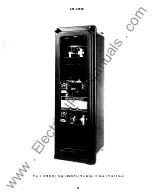
Страница 29: ...GEK 49849 F i g 1 8043474 Type JBCG51M Y1A Rel ay i n Case F ront Vi ew 29 w w w E l e c t r i c a l P a r t M a n u a l s c o m ...

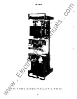
Страница 30: ...GEK 49849 F i g 2 8043475 Type JBCG51M Y1A Rel ay Out of Case F ront Vi ew 30 w w w E l e c t r i c a l P a r t M a n u a l s c o m ...

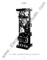
Страница 31: ...GEK 49849 F i g 3 8043476 Type JBCG51M Y1A Rel ay Out of Case Rear View 3 1 w w w E l e c t r i c a l P a r t M a n u a l s c o m ...

Страница 32: ...GEK 49849 I I LATE R F i g 4 Type JBCG77M Rel ay Out of Case Rear View 32 w w w E l e c t r i c a l P a r t M a n u a l s c o m ...

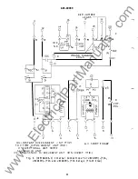
Страница 33: ...CURREN T UNI T CTOP TOC TI M E OVE R CU RRENT UNIT M I OJ D D I R ECTIO NAL UNI T B OT S l S EAL I N UNI T 6 C 3 P 3 p 7 8 1 0 S HORT F I NG E R F ig 5 0257A6195 0 I nternal Connecti ons for JBCG51M and JBCG53M Rel ays Front Vi ew 33 D P O T PO L w w w E l e c t r i c a l P a r t M a n u a l s c o m ...

Страница 34: ... U NI T C TQ P TOC TI M E OVE R C URREN T U N I T C M I OJ S H ORT F I NGER D D I R E CTIONAL UNI T B OT S l SEAL I N U N I T I OC ND I N S TA N T OV ERC U R R E N T U NI T NO N DI R EC T C M I D F i g 6 0257A6196 l I nternal Connecti ons for JBCG51M YlA JBCG53M Y1A and JBCG99H Y1A Rel ays Front Vi ew 34 I OC c r D P O T P O L w w w E l e c t r i c a l P a r t M a n u a l s c o m ...

Страница 35: ...IT TOP T OC TI ME O V E R C U RR E N T U NI T M ID 0 D I R EC T I O N A L U N I T B O T S I S E AL I N U Nl T R ED J U M PER L E ADS 1 9 I O C C l C3 7 9 P3 0 p4 P O T P O L 1 0 S HO RT F I N G E R F i g 7 0257A6197 0 I nternal Connecti ons for JBCG77M Rel ay F ront Vi ew 3 5 w w w E l e c t r i c a l P a r t M a n u a l s c o m ...

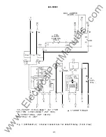
Страница 36: ...rs NOT USED DO NOT CONN ECT TO STUD 7 8 67N J BCG51 53 OR 77 I OC I NSTANTANEOUS OVERCURRENT UN I T TOC T I ME OV ERCURRENT UN I T D D I RECT I ONAL UN I T T S I TARGET S EA L I N UN I T 5 I Q_ A 67N B D f 7 N u C t t V 1 0 0 1 TO TRANS FO RMER N E U TRAL 1 67N 52 l i 67N S l F i g 8 0148A4012 3 Typi cal External Connecti ons D i agram for Rel ay Types JBCG51M JBCG53M or JBCG77M 36 w w w E l e c t...

Страница 37: ... CURRENl POLA IZATION rs NOT USED 00 NOT CONNECT TO STUD 7 8 LEGEND 1 _ _ _ _ _ 67N JOCG51 53 OR 77 l I OC I NSTANTANEOUS OVERCURREMT lM I T TOC TIME OVERCURRENT UNtT 1 6 6 7 N D D I RECT I ONAL UN I T T SI TARGET SEAL IM UN IT 1 7 IO C N Dh 11 __ J F i g 9 0273A9058 0 Typ ical External Connecti on Di agram for Rel ay Types JBCG51M Y1A and JBCG53M YlA 37 I t 67N ST w w w E l e c t r i c a l P a r ...

Страница 38: ...Rel ay I I P L A R Z E DI I I F P O T E N T I AL MU LT I P L ES O F P R O DU C T P I C K U P Ep l 0c o s 6 0 J J 6 I F C U R R E N T P O LAR I Z E D 1 0 1 p c o s M U L T I P LE S O F P R O DU CT P I C K U P o 25 I f D U A L P O L AR I Z ED M U LT I P LE S O F P RO D U C T P I C K U P E I c o s 6 0 p 0 f 1 cos 0 r I 3 6 AN G L E B Y WH I CH 1 0 LAGS Ep AN G LE BY WH I CH I 0 LAG S l p Ep P O LA R ...

Страница 39: ... oJ s o 1 0 1 2 1 0 80 2 o 2 5 3 o 4 o 5 o 6 o o s o t o o 1 2 1 6 20 1 6 0 _ I 10 r 9 r 8 7 VI r 01 c 4 _ 3 Q _ en 2 0 _ t 1 t 0 t I Q E 1 _ g 8 1 8 8 1 I _ADJ U Tt _EHlL I N ST UN I T CON T I NUOU S LY ADJUSTABLE 1000 800 100 700 100 500 400 300 200 100 80 10 10 50 40 30 20 10 8 1 1 01 01 07 01 05 04 03 H 01 I I 7 I 8 1 4 5 1 10 20 30 40 10 80 70 80 90 I I I I Ul MULT I PLES OF R E L AY TAP S ET...

Страница 40: ...1 3 o 4 O 5 0 6 a 7 a 8 o_ 1 0 1 2 2 0 2 5 3 0 4 0 5 01 6 0 7 Q 8 0 1 0 0 1 2 1 6 f f 0 r K 1 r 10 9 I 8 f 7 Ill f f 6 co 5 c 4 1 4D rn 3 r _ 0 2 0 I r 4D E I t h 1 2 I I I I I I III I IT ADJU STI ENTS I N ST U N I T CON T I NUOU SLY A UJ U STABLE I 7 110 I 7 I II 10 1I I I f 1 I I I I iJ 41 II I I 7 I I 1 4 I I 7 I I ll 10 41 II 10 70 1010 I I I I I Ill I I I r l lllf MULT I P L E S OF REL AY TAP...

Страница 41: ... 5 2 O 2 5 3 O 4 O 5 O 6 O 7 0 8 0 I 0 1 2 2 o 2 5 3 o 4 o 5 0 6 o o s o 1 o o 1 2 1 5 1 1 I 1 0 I 10 r f 9 8 __ r f 7 6 en r 5 E 4 1 t 3 Q __ 1 2 c b 0 l Q t I E 2 1 I 8 8 0 0 n i i L ADJ USTMENTS I H ST U N I T CON T I NUOU SLY DJU ST ASL E 5 7 8 1 4 5 1 10 20 30 40 50 80 70 8010 il i II I I I U UI M ULTI PLE S O F R E L AY T AP S E T T I N G F i g 14 088880274 5 Time current Characteri stic of ...

Страница 42: ... j__ _ t I I C 6roo l I I I I I l I I i I I I I I I I I I I 1 j I I t 1 I I I I I 1 II l 1 i il l J I i i 1 i 4 x__ ____ I I l I I I I I I I I I I I I I I l 3Y1 1 I I i I i I i I r t I i t I 1 I t I I I I i I I I j l I r I I J I l l I I I l j r I I N I i t I I I l I I r 1 t I I J I I I I l n v _ I Q IL l c I J j n lr J J I i l i I I CD I I F i g 15 0285A6663 Representati ve Time current Characteri...

Страница 43: ...I J I en I II I UJ C J _____ t i I I I I a z ttS I i I 1 I I 1 l i l i 1 ___ T _ ffi t _J 1 u UJ en I i f y 1 1 1 v 0 0 0 SON003S N l 3W il dO I d J tn 8 1 J I F i g 16 0208A8695 l Time current Character i sti c of the Non directi onal ly Control l ed I n stantaneous Overcurrent U n i t 43 t w w w E l e c t r i c a l P a r t M a n u a l s c o m ...

Страница 44: ...I I I I I I I PERCENT OVERREACH 100 YJ i t t i r i A PftkUP lJRRENT GRAWALLY APPLI ED __ 1 50 I I 8 CURRENT SJDOENLY APPLI ED I t I _j II I I li I i 1 t 1 __ I tn t _ _ _ 1 I j LU I I 1 11 30 i t I r CHIMr c 1 t I 0 LU 0 t I 20 t t PICK UP 1 t I I 10 L t llv I I I l MAXIM t1 iI t t 1 0 I 2Q 30 ij I 50 ANGLE IN CEffi EES LAG r 60 7tt PICK UP CHI SEISMIC I I Ell 1 91 c I TI I j lo 1 0 co w E l e c t...

Страница 45: ...Contact T i p H Brush Reta i ner L F E F Bu tton Contact T i p G Mov i ng Con ta c t Brush Re ta i ner A B _ _ _ _ _ c K Stati onary Con tact Support L Mo un t i ng S crew M Locknuts F ig 18 8023399 and 8027689 Low Gradi ent Contact Assembly for the Direct i onal Uni t 45 w w w E l e c t r i c a l P a r t M a n u a l s c o m ...

Страница 46: ... B STA J N L ESS ST E E L B A L L C D I A PH RAM F FLA T S P I RA L SPRI N G G C O N TA C T F i g 19 K 6077069 4 1 Barrel Contact Assembly for the D i recti onal and the I nstantaneous Overcurrent Uni t 46 F G w w w E l e c t r i c a l P a r t M a n u a l s c o m ...

Страница 47: ... B A R NOT E A F T E R E N G A G I N G AU X I L I ARY B R U S H CO N N ECTIN G PL U G T R AV E LS Y4 I N C H B E FO R E E N G A G I NG T H E M A I N B R U SH O N T H E T E R M I N AL B LO C K F i g 20 8025039 Cross Secti on of Drawout Case Showing Pos i ti on of Auxi l i ary Brush 47 w w w E l e c t r i c a l P a r t M a n u a l s c o m ...

Страница 48: ...12 14 16 18 20 TYPE XLA13 TEST PLUG 1 3 2 4 ADJ RES 5 7 9 6 8 10 TYPE XLA13 TEST PLUG TO T I MER START 120V RATED FREQ F i g 21 Ol78A9036 0 Test Connecti ons for Check i ng the TOC Uni t 48 w w w E l e c t r i c a l P a r t M a n u a l s c o m ...

Страница 49: ...13 TEST PLUG 3 4 CD 5 6 TYPE XLA13 TEST PLUG 7 8 19 20 9 10 F ig 22 0178A9037 0 Test Connecti ons for Check i ng P i ckup of Directi onal Uni t U s i ng Current Pol arizat i on 49 120V RATED FREQ w w w E l e c t r i c a l P a r t M a n u a l s c o m ...

Страница 50: ... 2 3 4 L TYPE XLA13 TEST PLUG 5 6 GEK 49849 17 18 7 8 19 20 RES 9 10 F ig 23 0178A9038 0 Test Connecti ons for Check i ng P i ckup of Di recti onal Un i t Us i ng Potential Pol arizat i on 50 w w w E l e c t r i c a l P a r t M a n u a l s c o m ...

Страница 51: ...ST PLUG RELAY TYPE CONNECT A J BCG 51 12 53 12 77 12 52 13 54 13 78 13 BLOCK D I RECT UN I T CONTACTS CLOSED I o B 19 _ 19 19 19 19 19 F i g 24 Ol78A9035 0 Test Connecti ons for Check i ng P i ckup of Direct i onal ly Control led IOC Uni t 51 120V RATED FREQ w w w E l e c t r i c a l P a r t M a n u a l s c o m ...

Страница 52: ...9 1 7 1 5 1 3 1 1 0 0 0 0 0 0 0 0 0 0 1 9 8 7 5 2 0 1 8 1 6 1 4 1 2 5 05 MM S T U D NUMBER I NG 9 7 5 3 1 0 0 0 0 0 0 0 0 0 0 1 0 8 6 4 2 BACK V I EW C U TO U T S MAY REPLACE DR I L L E D HOLES P A r JE L D R I L L I NG FOR SURFACE MOUNT I NG F R O N T V I EW 5 1 6 1 8 S T U D I NC H E S MM V I EW SHOW I NG ASSEM B L Y OF HARDWARE FOR SURFACE M T G ON S T E EL PANELS F i g 25 K 6209276 5 Out l i n...

Страница 53: ... r 1 r 1 r 2 4 IOC INSTANT OV E R C U R R ENT U N IT TOP TOC T I M E O V E R CU R RENT U N I T M I DDLE 0 DIR ECT O NAL U N IT BOTTOM Sf SEAL I N U N IT d 8 1 0 S H ORT FI N GER F i g 26 0273A9548 l I nternal Connections Di agram for the JBCG52M and the JBCG54M Rel ays 53 w w w E l e c t r i c a l P a r t M a n u a l s c o m ...

Страница 54: ...z t I a t 1 D P 3 P 4 r 9 8 1 0 I O C I N STANT OVERCU R RENT U N IT TOP I O C c l D POT PO L TOC TIME OV ERCU R RE NT UNI T M IDDLE D D I RECT I O NA L UN I T BOTTOM S I S E A L I N U N IT SH ORT F I N GE R F i g 27 0273A9550 I l l I nternal Connect i ons Di agram for the JBCG78M A Rel ay 54 w w w E l e c t r i c a l P a r t M a n u a l s c o m ...

Страница 55: ...w w w E l e c t r i c a l P a r t M a n u a l s c o m ...

Страница 56: ... 5 94 1100 4 93 4 92 7 89 6 85 11 81 Protection and Control GE Technology Center 205 Great Valley Parkway Malvern Pennsylvania 1 9355 1 337 I I w w w E l e c t r i c a l P a r t M a n u a l s c o m ...

Отзывы: