


1
2
3
* 4
* 5
* 6
* 7
* 8
* 9
RESET COIL
OPERATING
VOLTS
COIL VOLTS
125
125
4 8
4 8
250
250
4 8
250
4 8
230/60Hz
230/60Hz
230/60HZ
120/60Hz
250
115/60Hz
115/60HZ
115/60Hz
125
GEI-68720
*TABLE I X
RESISTANCE
RESISTANCE
EXTERNAL
OF RESET
OF OPER.
RESISTOR
COIL
COIL OHMS**
OH�1S**
185
2, 000
100
26
366
50
74 0
8, 000
200
26
8, 000
200
26
52. 8
1650
185
52. 8
1650
26
8, 000
200
26
13
200
26
2, 000
100
** Resistance and c�pacitance values are nominal; variation is � 10%
RECEIVING, HANDLING AND STORAGE
CAPACITOR
11F**
5
15
5
5
5
5
5
5
5
These relays, when not included as a part of a control panel, are shipped in
cartons designed to protect them against damage.
Immediately upon receipt of a
relay, examine it for any damage sustained in transit.
If injury or damage
resulting from rough handling is evident, file a damage claim at once with the
transportation company and promptly notify the nearest General Electric Sales
Office.
Reasonable care should be exercised in unpacking the relay in order that none
of the parts are injured or the adjustments disturbed.
If the relays are not to be installed immediately, they should be stored in
their original cartons in a place that is free from moisture, dust and metallic
chips.
Foreign matter collected on the outside of the case may find its way inside
when the cover is removed and cause trouble in the operation of the relay.
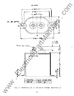
INSTALLATION
Type HFA relays should be mounted on a vertical surface.
The outline, panel
drilling diagrams, and internal connections are shown in Figs. 4 to 13.
Surface
mounting on steel panels requires an insulating bushing for each terminal.
PERIODIC CHECKS AND ROUTINE MAINTENANCE
In view of the vital role of relays in the operation of power systems, it is
important that a periodic test program be followed.
It
is recognized that the
interval between periodic checks will vary depending upon environment, type of relay
and the user's experience with periodic testing.
Until the user has accumulated
enough experience to select the test interval best suited to his individual
requirements, it is suggested that the pickup voltages and condition of contacts be
checked at an interval of from one to two years.
See the section on SERVICING AND
ADJUSTMENTS.
* Indicates revision
7
www
. ElectricalPartManuals
. com