GE HFA54 Скачать руководство пользователя страница 3

GEI-68720 

MULTI-CONTACT  AUXILIARY  RELAY 

TYPE  HFA54 

DESCRIPTION 

The  HFA54  relays  are  instantaneous,  hinged-armature,  multi-contact,  electric­

reset,  auxiliary  relays. 

Some  of  the  models  are  also  available  with  a  hand  reset 

feature  in  addition  to  the  electric  reset  feature. 

They  have  five  or  six 

electrically-separate  contact  circuits  adaptable  for  either  circuit-opening  or 

circuit-closing-applications. 

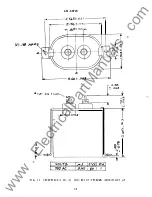
The  HFA  relays  are  available  for  front  or  back  connection.  The  front-connected 

relays  are  suitable  for  surface  mounting  only. 

The  back-connected  relays  are 

suitable  for  either  surface  mounting  or  semi-flush  mounting. 

Outline  and  panel 

drilling  dimensions  are  shown  in  Figures  7-10. 

Internal  connections  for  the  relays 

are  shown  in  Figures  4 ,   5,  and  6. 

APPLICATION 

The  HFA  relays  are  electric-reset,  hinged-armature,  instantaneous  auxiliary 

relays  that  are  suitable  for  application  where  the  operating  characteristics  and 

ratings  as  described  in  this  book  are  required. 

RAT! NGS 

The  TYPE  HFA  relays  are  available  with  coil  ratings  for  standard  voltages  up  to 

575  volts  at  25,  50  or  60  cycles,  and  up  to  250  volts  DC. 

The  operating  coil  is  continuously  rated  but  the  reset  coil  has  a  five 

(

5

second  intermittent  rating. 

The  current-closing  rating  of  each  contact  is  30  amperes. 

rating  is  12  amperes  continuous  or  30  amperes  for  one  minute. 

non-inductive  interrupting  capacity  of  each  contact. 

TABLE  I 

DC 

AC 

The  current-carrying 

Tab 

e  I 

is t s  the 

VOLTS 

AMPERES 

VOLTS 

AMPERES 

12 

30 

115 

30 

24 

1 5  

230 

20 

32 

10 

460 

15 

4 8  

575 

10 

125 

250 

www 

. ElectricalPartManuals 

. com 

Содержание HFA54

Страница 1: ...INSTRUCTIONS MULTI CONTACT AUXILIARY RELAY TYPE HFA54 GEI 68720G d Control GE Meter an Parkway 205 Great Val 55 0715 Malvern PA w w w E l e c t r i c a l P a r t M a n u a l s c o m ...

Страница 2: ...rovide for every possible contingency to be met in connection with installation operation or maintenance Should further information be desired or should particular problems arise which are not covered sufficiently for the purchaser s purposes the matter should be referred to the GeneralElectric Company To the extent required the products described herein meet applicable ANSI IEEE and NEMA standard...

Страница 3: ...onnections for the relays are shown in Figures 4 5 and 6 APPLICATION The HFA relays are electric reset hinged armature instantaneous auxiliary relays that are suitable for application where the operating characteristics and ratings as described in this book are required RAT NGS The TYPE HFA relays are available with coil ratings for standard voltages up to 575 volts at 25 50 or 60 cycles and up to...

Страница 4: ...th a specific contact arrangement they wi11 be shipped with six 6 circuit closing contacts code 60 However the HFA54D and HFA54 K relays are available with contact code 33 only as given in Table V The general characteristic of HFA54 relays are summarized in Table II TABLE II No Model Separate Additional Contact No Contact Characteristics Arrangement Circuits Table HFA54 B 5 Hand Reset III HFA54 C ...

Страница 5: ...H J L CODE NO 60 51 4 2 1 33 a a b b b a 24 POSITION NO CONTACT ARRANGEMENT 1 a a a a a 2 a a a a b 3 a a b b b 4 a b b b b 5 a a a b b 6 a a a a a TABLE V HFA54D K CODE NO 33 POSITION NO CONTACT ARRANGEMENT 1 a 2 a1 3 bl 4 b 5 b 6 a TABLE VI HFA54M N CODE NO 1 2 3 24 a b b b b a POSITION NO CONTACT ARRANGEMENT 1 a a a 2 a a b 3 b bl b1 4 a bl b 5 a a a 6 a a a 5 15 b b b b b a 15 06 b b b b b b b...

Страница 6: ...owever the charged external capacitor has sufficient energy to back up the operating coil to ensure proper latch holding of the armature See Figs 11 12 and 13 for outlines of the external capacitor and resistor BURDENS The operating coil burdens 1 isted Table VII are measured with the relay in the picked up position at rated voltage and are for continuous rating The common AC and DC burden table V...

Страница 7: ...bed If the relays are not to be installed immediately they should be stored in their original cartons in a place that is free from moisture dust and metallic chips Foreign matter collected on the outside of the case may find its way inside when the cover is removed and cause trouble in the operation of the relay INSTALLATION Type HFA relays should be mounted on a vertical surface The outline panel...

Страница 8: ...nce if a contact is changed from circuit opening to circuit closing the following checks and adjustments should be made 1 Make sure that all contact and coil studs are tight 2 Make sure that the armature is free of binding when operated by hand The braided 11pigtail11 lead on all contacts must be adjusted to exert minimum force on the contacts 3 Make mechanical contact adjustments as follows 3 1 N...

Страница 9: ...mately 1 8 gap between the stop screw and armature Lock the stop screw in this position The main coil should be adjusted to pick up at 80 of rated voltage for AC relays and 60 of rated voltage for DC relays This adjustment may be obtained by unseating the knurled adjusting nut at the lower end of the armature and turning this nut in a clockwise direction to raise the pickup The pickup is decreased...

Страница 10: ...GEI 68720 ltlltlll FIG l 8025534 HFA54 RELAY BACK CONNECTED SURFACE MOUNTED FRONT VIEW 10 w w w E l e c t r i c a l P a r t M a n u a l s c o m ...

Страница 11: ...GEI 68720 FIG 2 8025781 HFA54 RELAY FRONT CONNECTED SURFACE MOUNTED FRONT VIEW 11 w w w E l e c t r i c a l P a r t M a n u a l s c o m ...

Страница 12: ...GEI 68720 FIG 3 8025539 HFA54 RELAY BACK CONNECTED SEMI FLUSH MOUNTED FRONT VIEW 12 w w w E l e c t r i c a l P a r t M a n u a l s c o m ...

Страница 13: ...IG 4 0104 A8528 5 INTERNAL CONNECTIONS OF HFA54B HFA54 C HFA54 0 and HF54 E RELAYS BACK VIEW POS 6 RESET 1 COIL 5 7 11 4 2 9 POS POS POS 4 3 2 6 8 10 12 INTERNAL CONNECTIONS BACK VIEW 13 14 FIG 5 6375837 4 INTERNAL CONNECTIONS OF HFA54H HFA54 J HFA54 K and HF54 L RELAYS BACK VIEW 13 w w w E l e c t r i c a l P a r t M a n u a l s c o m ...

Страница 14: ...CONTACT LONG WIPE b N C CONTACT bl N C CONTACT LONG WIPE 6 POS I O ALT c O N N FoR AATf D AC VOL i r I I I 1 I I ll RATEDI C t f I 15 8 os I 12 _ I _ INTERNAL CONNECTIOHS BACK VIEW c J XT R S FIG 6 0207A7851 4 INTERNAL CONNECTIONS OF HFA54M AND HFA54 N BACK VIEW Revised since last issue 14 w w w E l e c t r i c a l P a r t M a n u a l s c o m ...

Страница 15: ...__L_ a N O CONTACT a 1 N O CONTAC LONG WIPE b N C CONTACT b1 sN C CONTACT LONG WIPE LONG WIPE CONTACTS OJ ERLAP t EACH REtAY IS AVAI B ONLl TH CONTAC T C DE SPEC 5 3 s 5 4 4 6 POS 3 7 9 J 2 1 8 11 12 INTERNAL CONNECTIONS BACK VIEW OPER COl r EACH CONTACT CONVERT IBLE ONLY CCORDING TO CONTACT ARRANGEMENT CODE FOR MODELS AS Ll STED FIG 7 0362A0576 7 OUTLINE AND PANEL DRILLING DIAGRAM FOR HFA54B C D ...

Страница 16: ... u OUTL IfE GEI 68720 TOP Of PU L DRILLI FIG 8 04 18A0799 8 OUTLINE AND PANEL DRILLING DIAGRAM FOR HFA54 RELAYS FOR SEMI FLUSH MOUNTING TYPICAL MODEL NUMBER IS HFA54B F 16 w w w E l e c t r i c a l P a r t M a n u a l s c o m ...

Страница 17: ... MOUNTING TYPICAL MODEL NUMBERS ARE HFA54 B H AND HFA54M H I l 6 32 11 41 5 32 OUTLINE 18 111 TYPE OF PANEL I NSULAT lNG STEEL 8 Dl A 16 I 2 HOLESI A 8 c 11 16 7116 3t 9116 11 16 h FIG 10 6375836 5 OUTLINE AND PANEL DRILLING DIAGRA M FOR HFA54H J K AND L RELAYS FOR SURFACE OUNTING TYPICAL MODEL NU MBER IS HFAS4H1 H 17 w w w E l e c t r i c a l P a r t M a n u a l s c o m ...

Страница 18: ... 1 5 3 03 ____ 1 4 Z l5 n31 81 031 WI 3 00 0 3 tM 12 24 I 4 38 0 3 T iD t l 0 0 1__ Wo I 0 I N M f It _1 Y f FIG 11 0028F0910 0 SH 2 OUTL INE OF EXTERNAL CAPACITOR 5 F 18 w w w E l e c t r i c a l P a r t M a n u a l s c o m ...

Страница 19: ... 188 HtJI ES GEI 68720 4 125 031 1 5 031 _ S T 0 31 14 4 3 C63 12 24 THD 438 010 3 0 3 0 FIG 12 0028F0915 0 SH 2 OUTLINE OF EXTERNAL CAPACITOR 15 F 19 w w w E l e c t r i c a l P a r t M a n u a l s c o m ...

Страница 20: ...GEI 68720 __ HOLE 32 1 2 9 32 FIG 13 0389A0752 2 OUTLINE OF EXTERNAL RES IS TOR US ED WITH HFA54M and HFA54 N RELAYS 20 w w w E l e c t r i c a l P a r t M a n u a l s c o m ...

Страница 21: ...w w w E l e c t r i c a l P a r t M a n u a l s c o m ...

Страница 22: ...w w w E l e c t r i c a l P a r t M a n u a l s c o m ...

Страница 23: ...w w w E l e c t r i c a l P a r t M a n u a l s c o m ...

Страница 24: ... 91 500 Meter and Control Business Department General Electric Company Protection and Control 205 Great Valley Parkway Malvern Pennsylvania 19355 0715 w w w E l e c t r i c a l P a r t M a n u a l s c o m ...

Отзывы: