


www.ge-security.com/industrial
12345 SW Leveton Drive
Tualatin, OR 97062
Phone: 800-247-9447
Fax: 503-691-7563
GE Security
Industrial
©2004 GE Security Industrial. GE Security Industrial reserves the right to change specifications without notice.
SI-3901-0204 14107 Rev
C
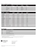
Ordering Information
PART NUMBER
TAMPER PROOF SCREWS & SCREWDRIVER
1953
#6 x 3/4"L Tampruf
Roundhead Screw
1954
#8 x 1-1/2"L Tampruf Roundhead Screw
1955
Tampruf
®
Screwdriver
1956
Tampruf
®
1/4" Drive Bit for #6 and #8 Screws
PART NUMBER
1
CONTACT
2
SENSE RANGE
3
SENSE RANGE
3
BREAK
LEAD LENGTH
341 or 343
CONFIGURATION
MINIMUM
MAXIMUM
RANGE
NOMINAL
341-BT-06(J)(K)
DPST: 1 N.O., 1 N.C.
0.12"(0.3cm)
0.38"(1.0cm)
0.75"(1.9cm)
6' (1.8m)
341-BT-12(J)(K)
DPST: 1 N.O., 1 N.C.
0.12"(0.3cm)
0.38"(1.0cm)
0.75"(1.9cm)
12' (3.6m)
341-BT-20(K)
DPST: 1 N.O., 1 N.C.
0.12"(0.3cm)
0.38"(1.0cm)
0.75"(1.9cm)
20' (6.1m)
341-BT-25(K)
DPST: 1 N.O., 1 N.C.
0.12"(0.3cm)
0.38"(1.0cm)
0.75"(1.9cm)
25' ( m)
341-BLT-06(J)(K)
DPST: 1 N.O., 1 N.C. w/LED
0.12"(0.3cm)
0.38"(1.0cm)
0.75"(1.9cm)
6' (1.8m)
341-BLT-12(J)(K)
DPST: 1 N.O., 1 N.C. w/ LED
0.12"(0.3cm)
0.38"(1.0cm)
0.75"(1.9cm)
12' (3.6m)
341-B3T-06(J)
TPST: 2 N.O., 1 N.C.
0.12"(0.3cm)
0.38"(1.0cm)
0.75"(1.9cm)
6' (1.8m)
341-B3T-12(J)
TPST: 2 N.O., 1 N.C.
0.12"(0.3cm)
0.38"(1.0cm)
0.75"(1.9cm)
12' (3.6m)
341-B3T-20(J)
TPST: 2 N.O., 1 N.C.
0.12"(0.3cm)
0.38"(1.0cm)
0.75"(1.9cm)
20' (6.1m)
341-B3T-25(J)
TPST: 2 N.O., 1 N.C.
0.12"(0.3cm)
0.38"(1.0cm)
0.75"(1.9cm)
25' ( m)
341-B3T-30(J)
TPST: 2 N.O., 1 N.C.
0.12"(0.3cm)
0.38"(1.0cm)
0.75"(1.9cm)
30' ( m)
341-B3LT-06(J)
TPST: 2 N.O., 1 N.C. w/LED
0.12"(0.3cm)
0.38"(1.0cm)
0.75"(1.9cm)
6' (1.8m)
341-B3LT-12(J)
TPST: 2 N.O., 1 N.C. w/LED
0.12"(0.3cm)
0.38"(1.0cm)
0.75"(1.9cm)
12' (3.6m)
CIRCUIT NUMBER
CIRCUIT
CONTACT
LOAD
SWITCHING
SWITCHING
TYPE
CONFIGURATION
RATING
VOLTAGE AC/DC
CURRENT AC/DC
1
Switch: S1
N.O.
10W/VA
48VAC/VDC
0.2A
2
Tamper: S2, S3, S4
N.C.
10W/VA
48VAC/VDC
0.2A
2
w/optional LED: D1
N.C.
0.1–1.4W
48VDC(3V drop)
30mA
4
Monitor: S5
N.O.
10W/VA
48VAC/VDC
0.2A
Electrical Specifications
Accessories
Warning— Each electrical rating is an individual maximum and cannot be exceeded!
1
The part numbers 341 and 343 are the same in all respects except the conduit connection exits, 341 left and 343 right. Not all models available in 343.
2
Configuration with actuator away from the switch
3
Proximity of ferrous materials usually reduces sense range — typically by 50%. The shape and type of material cause a wide diversity of effects.
Testing is required to determine actual sense range for specific applications.


