


58
Chapter 10: Diagnostics and Troubleshooting
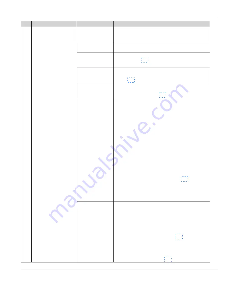
ID
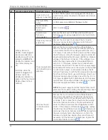
Symptom Description
Possible Causes
Actions & Solution
S1
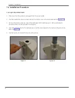
When system is in
standby mode (plugged
into power outlet and
standby/on switch is not
pressed yet),
BOTH
the
standby/on indicator and
hour meter display are
off.
(Normally, when the
system is plugged into
a power outlet, the
standby/on indicator is
green and the hour meter
display shows an hour
number.)
Power cord is not
properly connected.
Confirm that the power cord is plugged into the power
outlet and securely connected to the power inlet module
of the system.
No power at the
outlet.
Confirm power is available at the power outlet.
Fuses are open
(defective) or
missing.
Refer to section 10.1.
A system wire
harness is
disconnected.
Remove the unit cover and check whether all the wire
harnesses are properly plugged and connected. Refer to
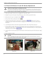
Power entry module
is defective.
Remove the unit cover and measure the AC input to
the power supply. Replace the power entry module if
necessary. Refer to section 11.6.
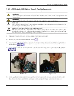
Power supply board
/ LED driver board is
defective.
Remove the cover and measure the voltage between
GND and -12V test points on the LED driver board using
a multi meter. Confirm if the voltage is within the -12V +/-
0.15 range. If not, remove the AC power and then unplug
the DC harness coming from power supply board at LED
driver board side. Restore AC power and then re-measure
voltage at the harness connectors. If the voltage is now
within the range, replace the LED drive board (Refer to
section 11.7). Otherwise, remove the LED driver board
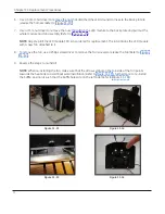
and: a) disconnect the DC harness from the power supply
board and perform the wire continuity test on the harness
to confirm the harness is not defective. Replace the DC
harness if necessary. b) with the DC harness disconnected
from the LED driver board, use a small screw driver to set
the power supply output voltage to be within the -12V +/-
0.15 range by adjusting R13 potentiometer on the power
supply board. If the output voltage cannot be set, replace
the power supply board (Refer to section 11.8).
NOTE:
The power supply board has internal short circuit
protection that could be limiting the output voltage due to
a short circuit in the load (LED driver board).
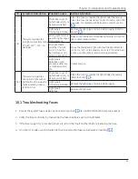
LED driver board
/ Control board is
defective.
Remove the cover and measure the voltage between
GND and V+ test points on the LED driver board using
a multi meter. Confirm if the voltage is within the 5V +/-
0.3 range. If not, remove the AC power and then unplug
the control harness from the control board. Restore AC
power and then re-measure the voltage between GND
and V+. If the voltage is still outside of the range, replace
the LED driver board (Refer to section 11.7). Otherwise, a)
disconnect the control harness on both ends and perform
the wire continuity test on the harness to confirm the
harness is not defective. Replace the control harness if
necessary. b) If the harness is not defective, replace the
control board. Refer to section 11.5.
Содержание Giraffe Blue Spot PT Lite
Страница 1: ...Giraffe Blue Spot PT Lite Operation Maintenance and Service Manual GE Healthcare ...
Страница 7: ... 7 Part I Operation and Maintenance ...
Страница 8: ...8 Part I Operation and Maintenance This page is intentionally left blank ...
Страница 16: ...This page is intentionally left blank 16 Chapter 1 Product Overview ...
Страница 22: ...This page is intentionally left blank 22 Chapter 2 Product Setup and Operation ...
Страница 26: ...This page intentionally left blank 26 Chapter 3 Operator s Maintenance ...
Страница 32: ...This page intentionally left blank 32 ...
Страница 33: ... 33 Part II Service ...
Страница 34: ...34 Part II Service This page is intentionally left blank ...
Страница 44: ...44 Important Service Safety Information This page is intentionally left blank ...
Страница 50: ...This page is intentionally left blank 50 Chapter 7 Installation ...
Страница 55: ...Chapter 9 Calibration No calibration is required for the Giraffe Blue Spot PT Lite 55 ...
Страница 56: ...This page is intentionally left blank 56 Chapter 9 Calibration ...
Страница 72: ...This page is intentionally left blank 72 Chapter 11 Replacement Procedures ...
Страница 88: ...12 5 Wiring Diagram 88 Chapter 12 Service Parts ...
Страница 94: ...This page intentionally left blank 94 ...
Страница 95: ......


