background image

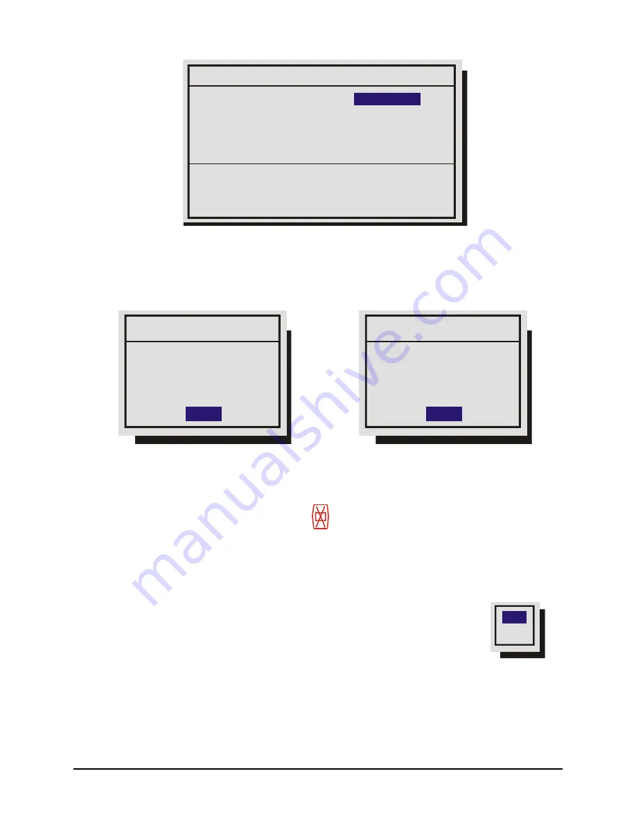
Disk Test Setup

Disk Test Result:             Disk Failed

   Disk 1: Write Error

   Disk 2: Write Error

Disk Test:                   

Test Frequency in hours:        0

Test Duration:               Fast

DISABLE

[CANCEL]  [OK]


Use the 

Jog 

to move between the menu fields and the 

Shuttle

 for the selections within the fields. 

When satisfied with the selections select 

OK

 and press the 

Enter

 button to execute. 

The Disk Test will run in the background and will not interfere with normal operations. Once the disk 
test is done, a message will appear on the screen indicating the test result.  


Disk Test Result

Disk Test Result

[OK]

[OK]

Disk Test Success

Disk Failure

Disk 1:Write Error

Disk 2:Write Error

PASSED

FAILED


Should a disk test fail, several actions will performed: 

• 

An icon will be displayed indicating disk failure. 

  It is displayed on Monitor A on the bottom of the 

screen in the middle. This icon will only disappear when the disk is replaced.  

• 

If the Notify Alarm or Notify Record email option is enabled in the 

Email Notification Setup 

Screen, 

an email will be sent indicating that a disk failure occurred. 


Main Menu 

 Record 

 Record Lock 

Use this menu to set the Record Lock feature. This feature disables the front panel  
record button. Setting Record Lock to ON will start the unit recording if it is not currently 
in the Record mode. 


ON

OFF

0150-0313B 40 

DVMRe


CT II 

Содержание DVMRe CT II

Страница 1: ......

Страница 2: ...LOSED PROGRAM IS FURNISHED SUBJECT TO THE TERMS AND CONDITIONS OF THIS AGREEMENT RETENTION OF THE PROGRAM FOR MORE THAN 30 DAYS OPENING OF THE SEALED WRAPPER IF ANY SURROUNDING THE PROGRAM OR USE OF THE PROGRAM IN ANY MANNER WILL BE CONSIDERED ACCEPTANCE OF THE AGREEMENT TERMS IF THESE TERMS ARE NOT ACCEPTABLE RETURN THE UNUSED PROGRAM AND ANY ACCOMPANYING DOCUMENTATION TO GE FOR A FULL REFUND OF ...

Страница 3: ... Playback 19 2 5 Recording 21 2 6 Display Options 22 2 7 Active Cameos 22 2 8 Sequencing 23 2 9 On screen Indicators 24 2 10 Triplex Mode 26 3 Menu System Overview 28 3 1 Menu Notation In This Manual 28 3 2 Accessing The Menu System 28 3 3 Available Menus 28 3 4 Menus In This Manual 29 3 5 Navigating The Menu System 29 3 6 Menu Shortcuts 29 3 7 The Main Menu 30 3 8 Time Date 30 3 9 Sequencing 33 3...

Страница 4: ...rded Alarms 71 5 Searching 72 5 1 Disk Analysis Screen 73 5 2 Motion Search 74 5 3 Search Filters 75 5 4 Retail Search 76 5 5 Search Results 79 6 WebBrowser 81 6 1 WaveBrowser Overview and Controls 82 6 2 DVMRe CT II WaveLink 84 7 Technical Specifications 86 8 RS232 Alarm Event Generation Text Insertion Protocol 88 8 1 Message Structure 88 8 2 Message Type 88 8 3 Alarm Event Fields 89 8 4 Alarm Ac...

Страница 5: ...10Macro Tables 93 10 1 Macro Functions Table 93 10 2 Scheduled Macro Table 94 10 3 Contacting technical support 95 10 4 Online publication library 95 0150 0313B 5 DVMRe CT II ...

Страница 6: ...Search for recorded images or events by alarm time date motion video loss camera number and ASCII cash register or ATM text Caution This products primary purpose is to furnish video multiplexing and recording Although the unit has alarm handling and motion detection functions they are considered secondary features This unit should not be the only alarm device on site Features Multiplexer functiona...

Страница 7: ...t is recommended that the Operator and Installer passwords be changed after installation is complete see section 3 20 Store the passwords in the administrator s secure files Default Passwords Four Channel Units Password Type Access Level Function Changeable by user Default Password Operator Operator Provides access to the Operator and SystemView menus Yes Press ENTER 4 Times Installer Installer Pr...

Страница 8: ...DVMRe CT II unit The Alarm Interface Circuit Board P N 0090 0077 Accessory PCB P N 0900 0127 Audio equipped models only The User Manual P N 0150 0193 A WaveReader Software CD P N 0151 0005 25W11 The WaveReader Software Manual P N 0150 0143 The Archiving Addendum P N 0150 0194 WaveWatch User Manual P N 0150 0189 Power Supply P N 4310 0020 Power Cords 120 VAC P N 4310 0002 and 220 VAC P N 4310 0001 ...

Страница 9: ...1 7 The Back Panel B B SVHS SCSI RS 232 1 AUX RS 485 1 10 100 ETHERNET RS 485 2 RS 232 2 1 2 3 4 5 6 7 8 9 10 11 12 13 14 15 16 12V DC 1 2 3 4 5 6 7 8 9 10 11 12 13 14 15 IEEE 1394 1 Camera Inputs BNC connector looping Auto Terminating 2 Composite Monitor A Output Composite video output with BNC style connector 3 Y C Monitor A Output Y C video output with 4 pin mini DIN style connector 4 Alarm I O...

Страница 10: ...ection 3 14 for information about disabling unused camera jacks in the menu system Composite Monitor Output When connecting directly from the DVMRe CT II to the monitor select the 75 Ohm impedance setting on the monitor Cable 75 Ohm Coaxial Connectors BNC If an additional device is connected to the monitor s looping output set the termination of the additional device as 75 Ohm and set the terminat...

Страница 11: ... can be activated by devices such as pressure pads passive infrared detectors door switches or other similar devices See section 3 11 for information about configuring the contacts as Normally Open or Normally Closed in the menu system Normally Open Zero Potential Relay Contact Configure in menu as Normally Open Normally Closed Zero Potential Relay Contact Configure in menu as Normally Closed TTL ...

Страница 12: ...fications to be correct at time of printing but no liability is assumed for omissions or errors NOTE AUX Port The back panel of the unit is equipped with an Aux Port DB 9 style connector Do not attempt to wire directly to the DB 9 connector on the back panel 1 5 6 9 DB 9 Connector on Back Panel Connect the Accessory PCB supplied with the audio equipped models to the AUX port to access the Audio fe...

Страница 13: ...on Straight Through PC Wiring Configuration Cross Over The cable connection configuration depends on your network configuration For a DVMRe CT II that connects directly to a Hub or Switch use a straight through connection For a DVMRe CT II that connects directly to a PC use a cross over connection Consult with your MIS personnel for the specific type of configuration See section 3 17 for informati...

Страница 14: ...ndum manual that is supplied with this unit Cable 6 position Firewire Connectors 6 position DIP Caution Ensure the power to DVMRe CT II is OFF BEFORE connecting any SCSI or 1394 devices Do not attempt to use the SCSI and 1394 ports simultaneously RS232 Port 1 For a Modem connection or remote control of unit See section 3 17 for information about configuring the modem settings in the menu system Se...

Страница 15: ...m installation is complete apply power in the following order 1 Energize the monitors and all of the cameras 2 Energize the DVMRe CT II Voltage 12 Volt DC Power 60 Watt 5 Amp Connector 2 1mm barrel center positive Once power is applied to the unit it will begin its power up procedure The unit will begin by displaying the software version on Monitor A then the unit will begin recording automaticall...

Страница 16: ...nformation about accessing and configuring the menu system see Section 3 To find detailed information in this manual about configuring each item in the QuickInstall menu use the following table to locate the main menu location of each item in the QuickInstall menu QuickInstall Menu Item Main Menu Location Section in Manual Change the time Main Menu Time Date Set Time 3 8 Change the date Main Menu ...

Страница 17: ...yback in Reverse 6 Freeze Button Freezes camera images on screen in Live mode Pauses Playback 7 Play Forward Button Begins Playback 8 Jog Shuttle Controls Playback speed and Menu selections 9 Menu Button Provides access to on screen menus 10 Power Indicator Indicates power on off condition 11 Alarm button Allows user to acknowledge and silence alarms 12 Sequence Button Sequences camera views 13 Zo...

Страница 18: ...information about programming the sequence list see section 2 8 For detailed information about configuring the dwell times in the menu system see section 3 9 Sequence Button Zooming To activate the 2x digital zoom select the full screen display of the camera you wish to zoom then press the Zoom button Zooming will be indicated by the LED located directly above the Zoom button Zooming is also indic...

Страница 19: ...ard operations press the Play Forward button Play Forward Button Reverse Play To begin reverse playback press the Reverse Play button Reverse Play Button Fast Forward During playback rotate the Shuttle the outer dial clockwise to view data at a higher than normal rate Increasing the amount of rotation increases the rate of playback Jog Shuttle AutoPause During playback moving the Jog the inner dia...

Страница 20: ...st and dwell times are programmable For detailed information about programming the sequence list see section 2 8 For detailed information about configuring the dwell times in the menu system see section 3 9 Sequence Button Zooming To activate the 2x digital zoom select the full screen display of the camera you wish to zoom then press the Zoom button Zooming will be indicated by the LED located dir...

Страница 21: ...ted directly above the Record button The unit always starts recording at the end of previously recorded data The unit will continue recording until the record button is pressed again Record Button Monitor Displays During Recording Multiscreen Live and Playback displays on Monitor A and Monitor B are not affected by recording operations LIVE PLAY BACK PLAY BACK LIVE LIVE LIVE LIVE LIVE LIVE Monitor...

Страница 22: ...ry for both Live and Playback multiscreen mode on Monitor A as well as Live multiscreen mode on Monitor B PIP Use the Jog Shuttle to adjust the location and size of the PIP display Please note that the PIP display is only available on Monitor A in Live mode when Monitor B is in fullscreen display mode PIP is disabled when SVHS is enabled on Monitor B See Camera Setup 2 7 Active Cameos A cameo is d...

Страница 23: ...equence Button Dwell Time The dwell time is the amount of time each camera is displayed on screen before advancing to the next camera The Full Screen and Multiscreen Dwell Times are separately programmable in the menu system For detailed information about configuring the dwell times in the menu system see section 3 9 Autolist Custom Sequence List The Autolist feature allows the user to create a cu...

Страница 24: ...s Time Date and Hard Disk record time left Conditional Indicators Displays indicators for Freeze Zoom Alarm Motion Detection Videoloss Autolist Program mode Macro Record and Macro Playback mode Status Display Box Displays Archive Device Network status and Image Quality Setting Playback mode only Text Display Box Displays ATM POS Text data Camera Titles Camera Titles are displayed on either the upp...

Страница 25: ...g the Camera Number button twice Status Indicators include On Live Fullscreen Archive Status Not Connected Not Ready Ready Ejecting Play and timeleft Timeleft indicates the amount of time before the archive medium is full Only available if the unit has Background Archiving turned On Network Displays all current Network connections Normal connection is displayed as ip ip or if there is no connectio...

Страница 26: ...enter the Triplex mode of operation When Reverse Play is pressed again the unit will revert back into the normal Playback mode While in the Triplex mode if forward play is in progress the Reverse Play button will change the playback direction Reverse Play Button Fast Forward During Triplex mode rotate the Shuttle the outer dial clockwise to view playback images at a higher than normal rate Increas...

Страница 27: ...g the Camera number button again displays the Status Display Box Pressing the same button a third time displays any associated ATM or cash register ASCII text Number Button Sequenced Full Screen Display While in a Full Screen display press the Sequence button to begin full screen sequencing The sequence list and dwell times are programmable For detailed information about programming the sequence l...

Страница 28: ...system are represented in the manual as follows Selected Not Selected Time Date Time Date 3 2 Accessing The Menu System Enter the menu system by pressing the Menu button A Password Box will appear on the primary monitor Enter either the Operator Password Providing limited access to the menu system Only the Operator and System View menus are available Menu Button Installer Password Providing comple...

Страница 29: ...e Jog to highlight items in the drop down menus Selecting Menu Items Hit the ENTER button to select the highlighted menu item Exiting Menus Press the Menu button to exit a menu From the menu bar press the Menu button to exit the menu system completely 3 6 Menu Shortcuts Zoom Button In menu lists that have 2 settings per camera the Zoom button will toggle all selections This provides a quick and ea...

Страница 30: ...t Savings Time Setup clock synchronization between Triplex and Network Server Main Menu Time Date Time Date Display Use this menu to specify if the time and date will be displayed on Monitor A Monitor B Both Monitors Not Displayed Rotate the Jog to navigate then rotate the Shuttle to change the values Save changes and exit the menu Select OK then press the Enter button Exit the menu without making...

Страница 31: ... press the Enter button Main Menu Time Date Set Date Date Setup CANCEL OK MM DD YY Day 01 25 60 MON 1 Press the Enter button the highlighting will move to the row of numbers 2 Enter the date in Months Days Years The day of the week is calculated automatically Rotate the Jog to change the values and the Shuttle to navigate 3 Press the Enter button to confirm the selection and exit the edit mode 4 T...

Страница 32: ...nday in October Includes Includes New Zealand RUS DST starts at 02 00 on the last Sunday in March DST ends at 03 00 on the last Sunday in October Includes Includes Russia The Time Zone must be set correctly to ensure that the DST adjustments are made at the right time It is also required for accurate email time stamping The clock will only be automatically adjusted once on a given time and date If...

Страница 33: ... next camera Main Menu Sequencing Multiscreen Dwell Rotate the Jog to change the desired dwell time from 1 to 30 seconds The default is 3 seconds Multiscreen Dwell Time in Seconds 03 1 Press the Enter button to confirm the selection and exit the menu 2 Press the Menu button to exit the menu without making changes Main Menu Sequencing Fullscreen Dwell Rotate the Jog to change the desired dwell time...

Страница 34: ...hard disk becomes full Main Menu Record Record Timer Use this menu to setup Preset Record Timer Events Day Start Stop Macro ON OFF 22 59 01 59 NONE ON MON FRI 05 56 04 06 10 ON 7 OK Hit ENTER to toggle EDIT Mode 1 Rotate the Shuttle to select a timed event from the list 2 Press the ENTER button to enter the Edit mode 3 Rotate the Shuttle to navigate to the desired field 4 Rotate the Jog to change ...

Страница 35: ...ime lapse Record Rate under normal conditions Records at the Event Record Rate during events Event Camera Settings Camera Type Event TL Pre Event Duration 00 Post Event Duration 000 Event Associated Cameras 01 CANCEL OK About Events An Event is an action that the unit acknowledges by recording at the Event Record Rate yet it is not cause for an Alarm Events may be created two ways via RS232 text i...

Страница 36: ...0pps NTSC 25pps PAL The bottom right corner of the menu contains a record duration calculator The top line indicates the estimated recording time for the unit in Time lapse record mode only The bottom line indicates the estimated recording time taking into consideration the amount of time the unit will spend in Activity Event and or Alarm record mode Timelapse Record Rate Camera 1 Camera 2 0 29 pp...

Страница 37: ...4 Time 4 1 Rotate the Jog to navigate and the Shuttle to change the values 2 To save changes and exit the menu Select OK and then press the Enter button 3 To exit the menu without making changes Press the Menu button or select CANCEL then press the Enter button Main Menu Record Activity Record Rate The unit will record at the Activity Record Rate when the camera is in normal Timelapse Record Mode ...

Страница 38: ...ess the Enter button Main Menu Record Alarm Record Rate During an alarm the unit records at the alarm record rate The bottom of the menu contains a record duration calculator The top line indicates the estimated recording time of the cameras in Alarm record mode only The bottom line indicates the estimated recording time taking into consideration the amount of time the unit will spend in Time laps...

Страница 39: ...ions then press the Enter button to begin Delete Delete all data from the hard disk with the possibility of restoring it Undelete Restore data that has been deleted but not yet overwritten Destroy Erase all data from the hard disk permanently without the possibility of restoring it Selecting this option brings up a confirmation dialog box Test Provides access to the Disk Test Setup menu which feat...

Страница 40: ...sult OK OK Disk Test Success Disk Failure Disk 1 Write Error Disk 2 Write Error PASSED FAILED Should a disk test fail several actions will performed An icon will be displayed indicating disk failure It is displayed on Monitor A on the bottom of the screen in the middle This icon will only disappear when the disk is replaced If the Notify Alarm or Notify Record email option is enabled in the Email ...

Страница 41: ...it Caution The DVMRe CT II s primary function is to furnish video multiplexing and recording with a multiscreen display Although the unit has alarm handling and motion detection functions these are considered secondary features This unit should not be the only alarm device on site Main Menu Alarms Input Configuration Configure the alarm inputs as either Normally Open or Normally Closed Configure i...

Страница 42: ...e input you wish to configure Freeze Selecting Yes will freeze the alarm camera display quadrant 1 at the time the alarm is activated Cameras This setting determines the four cameras displayed on screen when an alarm is received The camera group contains the camera in alarm and three associated cameras Default Settings The first camera in the list is the camera in alarm The second camera in the li...

Страница 43: ...a 4 in alarm 1 4 2 4 3 4 5 4 6 4 7 4 8 4 1 4 Main Menu Alarms Enable Disable Use this menu to Enable or Disable the alarm inputs Select from the following Enable All Disable All Individual Enable Individual Enable Allow the user to access the Alarm Enable submenu and enable or disable alarm inputs on a per camera basis Enable All Disable All Rotate the Jog to navigate and the Shuttle to change the...

Страница 44: ...Alarm Action Setup menu This menu selection is not available on 4 channel DVMRe CT II units since Fullscreen Alarm Mode is the only alarm mode available Fullscreen Alarm Fullscreen NO Main Menu Alarms Relay Configuration Use this menu to configure each relay output as either Relay Configuration CANCEL OK Relay 01 Relay 02 N CLOSED N OPEN Normally Open Normally Closed Main Menu Alarms Buzzer Setup ...

Страница 45: ...tores up to 5 seconds of recorded information in a buffer This data can be automatically retrieved when an alarm is activated Select the amount of time just previous to the activation of an alarm you wish to retrieve Pre Alarm Duration 05 Time in Seconds Main Menu Alarms Notification Use this menu to select TCP IP Email Email Alarm Notification TCP IP Notification Email Notification Setup This scr...

Страница 46: ...y Alarm is set to enable will the email include a link to the video on the disk The link pertains only to the alarm start For more information see section 6 2 Email Address Format The format of the email addresses should be entered as follows If the email address to be notified is john doe somecompany com then john doe should be entered in one of the Email User fields and somecompany com should be...

Страница 47: ...epends on the number of camera inputs 4 10 or 16 Each macro can have up to 32 keystrokes Timed Macro Start Edit Submacro Macro Record Use this menu to Enter Macro Record mode Program a scheduled start time for a macro Edit the RS232 command string for each submacro Main Menu Macro Macro Record Note Do not attempt macro programming while the front panel is locked To begin recording a macro Macro Re...

Страница 48: ...unction then 6 Reset Relay 2 output Function Function then Submacro number Program a specific submacro to activate when the macro is run Function then Enter End macro recording Macro Excluded Features The following core features or settings cannot be programmed by Macro Disk Maintenance Erase Archive Medium POTS Setting Ethernet Setting RS485 Network Address Front Panel Lock Unlock Record Timer Ma...

Страница 49: ...le running the macro is indicated on screen as the letter F and the macro number The user can cancel the macro at any time by pressing the Function button Function and Number Buttons Daylight Savings Time Alternate Method F To adjust the time one hour for daylight savings time press the Function button then the Sequence button If this function is activated during April one hour is added to the tim...

Страница 50: ...ou wish to configure Motion Detection Parameters Setup CANCEL OK Camera Motion Detection Type Sensitivity Relay Output Link to Event Rejection Target Size Link to Alarm 01 ACTIVITY 06 2 LOW 01 NONE Navigate in this menu using the Jog to select the field and the Shuttle to change the parameters Activity Vs Intrusion Activity Detection is a simple type of motion detection having only a sensitivity s...

Страница 51: ...ne clouds passing over The High setting will filter out sudden luminance changes as well as spurious motion events that do not persist for a number of frames a bird flying past the lens Target Size This setting is the minimum number of zones from the 16 x 16 grid that must be activated simultaneously before it is considered to be valid motion Link To Alarm Select the alarm number that you wish to ...

Страница 52: ... Use the Play Forward button to increase the sensitivity level and the Play Reverse button to decrease the sensitivity level The sensitivity level is also displayed as a numeric value Play Forward to increase the Sensitivity Play Reverse to decrease the Sensitivity Main Menu Motion Detection Indicate Detection Motion Detection may be indicated on screen by displaying the letter M Use this menu to ...

Страница 53: ... 3 Rotate the Shuttle to navigate the cursor in the camera title 4 Rotate the Jog to navigate the cursor in the character bank 5 Press the Number 1 button to insert a blank character or press the Number 2 button to insert the selected character 6 When finished editing the title press the Enter button to exit the edit mode 7 Save changes and exit the menu Select OK then press the Enter button 8 Exi...

Страница 54: ...ich inputs have video signals and which are experiencing videoloss When this feature is activated the unit will automatically disable the inputs experiencing videoloss The DVMRe CT II will also re enable video inputs that were previously disabled if a video input signal is detected Camera Disable CANCEL OK Camera 01 Camera 02 Enable Camera 03 Disable Camera 04 Enable Camera 16 Enable Disable Power...

Страница 55: ...s feature to analyze and optimize the video input signal Luminance Histogram Black 0 L White Luminance Main Menu Camera Setup MonB SVHS Use this menu to enable or disable SVHS output on Monitor B Select Enable or Disable from the menu and press Enter A confirmation screen will appear Select from Yes or No and press Enter The output of monitor B will change immediately When this feature is enabled ...

Страница 56: ...ds the unit to record data to both the hard disk and the archive device simultaneously Select from the following items OFF Turns background archiving Off ON Turns background archiving On ON OFF Main Menu Archive Setup Erase Archive Medium Use this feature to erase all of the recorded data on an archive device With Erase Archive Medium highlighted press the Enter button If a compatible archive devi...

Страница 57: ... RS232 Configure the network address for the RS485 network Configure the Ethernet address and networks settings Main Menu Communications RS232 Select the Port you wish to configure and press the ENTER button Port 1 Use this menu to Port 2 Port 1 Baud Rate POTS Setup Enable Disable POTS and configure the Modem initialization string POTS Setup Adjust the Baud rate POTS Setup The default modem string...

Страница 58: ...nd reboot select OK then press the Enter button The unit will only reboot if changes were made to the Modem Init String 9 To exit the menu without making changes select Cancel then press the Enter button Pressing the Menu button also exits the menu without making changes Baud Rate Use this menu to configure the baud rate for Port 1 Rotate the Jog to select a baud rate from the menu Save changes an...

Страница 59: ...ly addressed Name Service Select from Disable WINS or GnuDIP Enabling WINS registers the hostname and IP address within the current Network This ensures that you can connect to the Triplex by hostname within the network See the Note below for information on configuring Dynamic DDS with GnuDIP DDNS Update Interval Select the Dynamic Domain Name Server interval Select from Disable or from 1 to 1440 ...

Страница 60: ...number 0 When everything is configured correctly the DVMRe will send periodically a Dynamic DNS update message over TCP port 3495 to the Dynamic DNS server telling the server its hostname The DVMRe does not include its IP address in the message Instead the Dynamic DNS server extracts the IP address of the DVMRe via the Ethernet source IP address This guarantees that the correct IP address is used ...

Страница 61: ...ord Select OK then press the Enter button The unit will reboot returning all settings except the time date email addresses and email IP address to the factory defaults Due to the large size of the hard disk the reboot may take several minutes Change Language Language Password 10 and 16 Channel 5 4 1 5 4 Channel 1 4 1 4 From the Factory Setting menu enter the Language password A menu will appear di...

Страница 62: ...t Password The Ethernet Password feature limits access to only those users who access the unit using the password feature of WaveReader versions 2 3 or later When the unit is first setup the default is No Password Protection Meaning anyone using WaveReader and accessing with an ethernet connection can connect to the unit Password Box Enter a new Ethernet Password Activate The Ethernet Password 1 E...

Страница 63: ...lation is complete it is strongly recommended that as a minimum the items in the QuickInstall menu be configured before the unit is used All items located in the QuickInstall menu are also found in the Main menu These items are provided in the separate QuickInstall menu as a convenience for the installer Use the following table to find detailed information about configuring specific items from the...

Страница 64: ...nd detailed information about configuring specific items from the Operator menu Operator Menu Item Primary Menu Location Section In Manual Sequencing Main Menu Sequencing 3 9 Time Date Display Main Menu Time Date Time Date Display 3 8 Titles Display Main Menu Camera Setup Camera Titles Title Display 3 14 Alarm History Main Menu Alarm Alarm History 3 11 Video Archive Setup Main Menu Archive Setup 3...

Страница 65: ...he following tables The default values are bolded and italicized The View Screens View Screen 1 Alarm Input Enable Disable 1 Enabled 0 Disabled Normally Open or Normally Closed 0 Open C Closed Macro Macro number if activated Alarm Action Freeze 1 Freeze 0 No Freeze Cameras Primary camera in alarm and three associated cameras Relay 1 2 1 2 or None Intrusion AND OR AND OR View Screen 2 Camera Enable...

Страница 66: ...re Event Duration 0 to 5 seconds 2 Post Event Duration 0 to 200 seconds 0 Acitvity Record Rate In pictures per second pps 2 spp Record Quality High 8 7 8 9 Medium 4 5 6 or Standard 1 2 3 Event Associated Cameras Up to 3 View Screen 5 Record Timer DAY 1 31 Mon Tue Wed Thu Fri Sat Sun Mon Fri Sat Sun Mon Sun Start Time HH MM Stop Time HH MM Macro Macro Number On Off On or Off View Screen 6 Time and ...

Страница 67: ...its 4ch Yes Global Alarm Record Rate In pictures per second pps 30 pps Pre Alarm Duration In seconds 001 Archive Alarm Enable or Disable View Screen 8 Auto Disable On or Off Background Archive On or Off Monitor Setup Single or Dual Baud Rate Port 1 1200 1400 4800 9600 19200 38400 and 57600 Baud Rate Port 2 1200 1400 4800 9600 19200 38400 and 57600 Network Address 001 005 001 Ethernet Enable or Dis...

Страница 68: ...rver 3 18 173 13 TCP MTU Size Standard 1200 and 1400 Archive Port Select SCSI 1394 SVHS on monitor B Enable or Disable DDNS Update Interval Disable 1 1440 min 2 minutes HTTP Port 80 8080 View Screen 10 Disk Test Test Now Test Periodically or Disable Test Frequency in hours 0 1000 Test Duration Fast or Thorough Disk Test Results Disk Test Success or Disk Test Failed Bandwidth Unlimited 5 KB per sec...

Страница 69: ...cted Record Rate Record Rate can be increased by recording at the Alarm Record Rate see section 3 10 and by Interleaved or Exclusive Recording see Alarm Record mode in section 3 11 4 3 Alarm Acknowledge Pressing the Alarm button acknowledges to the unit that the alarm has been recognized and silences the internal buzzer This does not clear the alarm condition 4 4 On screen Displays During Alarms 1...

Страница 70: ...lay of all cameras in alarm 4 Channel Units Single Alarm Unit switches to a full screen display of the camera in alarm Additional Alarms Unit switches to a sequenced display of all cameras in alarm 4 5 Alarm Operations During Playback Live Alarms Displays Single Alarm Unit switches to a full screen display of the camera in alarm on Monitor B Additional Alarms Unit switches to a sequenced display o...

Страница 71: ... flashing red A in its cameo Alarm LED lights to indicate an alarm condition There is no change in the playback or Triplex multiscreen based on playback of recorded alarms 4 6 Alarm History Box The Alarm History feature provides a list of the 100 most recent alarms View the Alarm History Box by accessing the menu system and selecting Operator Alarm History The Alarm History Box can also be found u...

Страница 72: ...ity Event Alarm Text Retail Camera 1 2 3 4 5 6 7 8 9 10 11 12 13 14 15 16 Hit ZOOM to edit retail text list Hit ENTER to toggle EDIT Mode X X X X X X X X X X X X X X X X X X CANCEL START SEARCH EDIT MODE Start Date Start Time Days HH MM SS 001 01 21 2002 20 08 10 0 00 01 55 002 01 21 2002 20 09 10 0 00 00 38 003 01 21 2002 20 10 10 0 01 07 22 004 01 22 2002 20 07 10 0 00 00 07 005 01 23 2002 20 07...

Страница 73: ...2002 20 45 00 01 21 2002 20 17 01 Level 1 Disk Time and Date at cursor location Arrow Cursors Zoom Level Write to CD Record Button Rotating the Jog moves the two arrow cursors across the representation of the recorded video As the cursors move across the screen the corresponding disk time is indicated in the upper right of the screen The video representations are color coded by category Rotating t...

Страница 74: ...d Motion Search Last 2hrs Last 8hrs Last day Last 7 days Last 4 weeks Last 12 weeks Custom X Selecting any of the other options and pressing Enter starts playback and displays the Motion Search Setup Screen 5 This screen overlays the current playback video and allows the user to enable or disable motion detection on the screen within blocks that form a 16 x 16 grid Pressing the Function key while ...

Страница 75: ... 15 16 Hit ZOOM to edit retail text list Hit ENTER to toggle EDIT Mode X X X X X X X X X X X X X X X X X X CANCEL START SEARCH EDIT MODE The following options are available when an archive device is connected 1 Play from Disk 2 Play from Archive 3 Copy from Disk to Archive 4 Copy from Archive to Disk Hit Camera buttons to select deselect individual cameras Use the Zoom button to globally select de...

Страница 76: ...a category All strings below a category are interpreted as sub levels of that category until another category appears The creator of the retail text file is responsible to put the categories and sub levels into correct order The DVMRe will not sort the strings A category has to have at least one sub level The customer has to store this file as a txt file named retail_search txt Example filename re...

Страница 77: ...retail text file The user can download the retail text file to a PC by right clicking the link and by choosing Save Target As The user can only upload one retail text file and can delete the current retail text file After uploading the file and also after a reboot the DVMRe will read the contents of the file and store it in memory The Local Retail Search Screen Access to the Local Retail Search sc...

Страница 78: ...ear individual or all selected sub levels 3 categories 5 sub levels and 5 selected sub levels can be displayed on screen at one time Up down keys will scroll the screen backward and forward The user can select sub levels from different categories by first selecting the category then going to sub level frame and highlighting the selection The user selections are kept in non volatile memory so they ...

Страница 79: ... searching the Search Results window will appear A maximum of 200 results can be displayed per search Two types of Search Result windows will appear depending on the Operation and type of search that is performed Search Results 3 19 06 11 02 3 20 18 51 02 3 19 21 42 02 3 20 21 54 02 3 19 23 51 02 3 21 02 25 02 3 20 6 26 02 3 21 03 51 02 3 20 14 30 02 3 22 21 01 02 PLAY REV FWD to page up down ENTE...

Страница 80: ...erformed These options are not displayed When archiving the unit will not allow the amount of selected data to exceed the amount of space available on the target medium Press the Menu button to exit the Search Results window without making a selection Hitting the Enter button will play the selected search result Hitting the Enter button again while in playback will cause the next selection from th...

Страница 81: ...s and Initalize and Script ActiveX controls not marked as Safe are set to Prompt 6 Click the OK button 7 Click on the Yes button in the Warning message 8 Click the OK button in the Internet Options window NOTE To access the web interface 1 Launch Internet Explorer version 5 5 or later on any local Internet connected PC or laptop 2 Type in the Triplex s IP address or hostname in the address field a...

Страница 82: ...ble Disk volumes The Main Viewing Area Pictures are displayed in this area in Multi Camera and Single Camera formats Picture display order is according to the information encoded by the unit used to create the original video data file Choose from the following displays 16 way Multiscreen Display Large and Medium 4 way Display Single Camera Display Large Single Camera Display Medium Single Camera D...

Страница 83: ... 13 Connect Disconnect button Click on this button s to connect to the unit 14 Number buttons Press any of these buttons to call up individual cameras for display When connected to a unit that has more than 16 cameras right clicking over the number buttons will display numbers 17 through 32 Right click again to return to cameras 1 through 16 15 Single Camera Display Size Choose from Small Medium o...

Страница 84: ...ing example the options are in bold Example http 3 18 172 230 wrcontrollite_c 1s 2a 3t 1361959858 ssi The following table specifies the supported options Name Code Description Example Camera c n Describes either the camera number for fullscreen 1 Camera 1 16 Camera 16 or the type of the multiscreen display 100 Multiscreen 16 large 101 Multiscreen 16 small 102 Quad screen c 10 Size s n For fullscre...

Страница 85: ... Links The DVMRe CT II is able to send emails when certain events occur like videoloss alarms etc When in record mode the Triplex software version 5 00 will add a WaveBrowser link in the email notification It will only add a link in the email if Notify Alarm is set to enable and the link will only pertain to the Alarm start Clicking this link initiates WaveBrowser to be started make a normal conne...

Страница 86: ...inating Color Mono Monitor A Output Y C 4 pin Mini DIN Connector Monitor B Output Y C 4 pin Mini DIN Connector Monitor A Output Composite BNC Connector Monitor B Output Composite BNC Connector RS485 Port Two Looping RJ 45 Connectors SCSI Port 50 pin High Density SCSI 2 female connector IEEE 1394 Firewire Port 6 position IEEE 1394 Socket Alarm I O Port Use Supplied DB 25 PCB connector Video Video S...

Страница 87: ...ors Status Retrievable via RS232 port Motion Detection Zones Per Camera 256 16 x 16 grid Sensitivity Settings 10 levels Gray Levels Per Zone 256 levels Motion Detection Status Output Relay Outputs Link to Alarms Link to Events On screen Indicators Status retrievable via RS232 port Part Numbers Remote Keyboard CBR KB3 CBR KB3 J KTD405 Includes motorized pan tilt and zoom controls Rack Mount Kit CBR...

Страница 88: ...ent using Intel byte ordering Little Endian The Check Sum byte is the result of XORing all the bytes in the message Check Sum 8 2 Message Type 0xFF 0x14 0x40 Data Length 0 Data Length 1 Camera Alarm Event String 0 String 1 String n 1 One message is currently supported to store text along with recorded video CMD_NEW_ADD_TEXT Class byte is 0x14 Command byte is 0x40 Data Length is the number of data ...

Страница 89: ...E Every Start Alarm command should subsequently be followed with a Stop Alarm command at some point Failure to do so will render that alarm input useless even if the alarm was latched and gets acknowledged from the front panel A Stop Alarm followed by a Start Alarm will have to be sent to create a new alarm on that channel Stop Alarm 0000 10XXb If only the stop bit is set the selected camera s ala...

Страница 90: ...orded at the Event Record Rate Stop Event 0000 0010b If only the stop bit is set the current event on the selected camera will be terminated This will start the post event timer after which the selected camera will resume recording at the normal record rate Momentary Event 0000 0011b If both the start and stop bits are set a momentary event will be initiated on the selected camera Pre event video ...

Страница 91: ...1 Enter 42 Reserved 43 Macro 44 Reserved 45 49 Monitor B 50 Reserved 51 63 Left Arrow 64 Right Arrow 65 Up Arrow 66 Down Arrow 67 Reserved 68 74 Alarm and Sequence 75 Alarm and Camera 1 76 Alarm and Camera 2 77 Alarm and Camera 3 78 Alarm and Camera 4 79 Alarm and Camera 5 80 Alarm and Camera 6 81 Alarm and Camera 7 82 Alarm and Camera 8 83 Alarm and Camera 9 84 Alarm and Camera 10 85 Alarm and Ca...

Страница 92: ...i Requesting data from the DVMRe When a message of type 0xBB is sent to the DVMRe CT II it will respond by sending 16 bytes of requested data a Read Alarm History List Byte 1 0xFF Byte 2 0xBB Byte 3 0 Byte 4 0x09 When the Read Alarm History List message is received by the DVMRe CT II it responds by sending a start byte 0xFF followed by ASCII strings for every alarm event in its alarm history list ...

Страница 93: ...ecord of the programmed macro functions 10 1 Macro Functions Table Macro Number Description 1 2 3 4 5 6 7 8 9 10 11 12 13 14 15 16 Function Sequence Daylight Savings Time Sets clock ahead one hour in April and back one hour in October 0150 0313B 93 DVMRe CT II ...

Страница 94: ...10 2 Scheduled Macro Table Event Day Time Macro to Run 1 2 3 4 5 6 7 8 9 10 11 12 13 14 15 16 17 18 19 20 0150 0313B 94 DVMRe CT II ...

Страница 95: ... 24 hours a day Note Be ready at the equipment before calling for technical support 10 4 Online publication library Another great resource for assistance with your GE Security products is our online publication library available to all of our customers on our website To access our publication library go to our website at the following location http www gesecurity com In the Tools area at the top c...

Страница 96: ...0150 0313B ...

Отзывы: