background image

GE Zenith Controls

3

ZTG/ZTGD Operation and Maintenance Manual (70

R

-1000D)

Each GE Zenith transfer switch is factory wired and 
tested. A complete information package is furnished
with each switch which includes:

a.

Sequence of operation.

b.

Description and operation of 
all accessories supplied.

c.

Power panel connection diagram 
and schematic.

d.

Description and identification of 
all customer field connections.

Installation of GE Zenith transfer switches includes:

a.

Mounting the transfer switch cabinet.

b.

Connection of Source 1, Source 2, 
and Load cables or bus bars.

c.

Connection of external control 
circuits as required.

Mounting

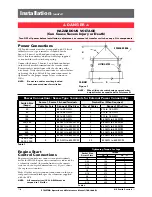
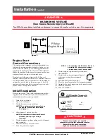
Adequate lifting means must be used to mount the
transfer switch into place. The recommended method for
moving the transfer switch using the lifting eyes, where
supplied, and a spreader bar is illustrated in Figure 1.
Enough room should be allowed to open the cabinet
doors fully for inspection and servicing of the switch per
NEC and local codes.

Safety / Installation

DANGER

HAZARDOUS VOLTAGE

(Can Cause Severe Injury or Death)

Turn OFF all power before installation, adjustment, or removal of transfer switch or any of its components.

The safe operation of your switch is 

GE

Zenith’s focus.

The proper storage, installation, operation and mainte-
nance will help increase the life of the switch.

Equipment Inspection
and Storage

Once you have received the transfer switch, inspect
it for any damage. This includes damage to the
enclosure, power panel, control panel and wiring
harness. If any damage is found or suspected, file a claim
as soon as possible with the carrier and notify the nearest

GE

Zenith representative.

Before installation, if it is necessary, store the transfer
switch in a clean dry place, protected from dirt and
water. Provide ample air circulation and heat, if neces-
sary, to prevent condensation.

5% to 95%

(non-con-

densing)

-30°C to

+75°C

(-22°F to

+167°F)

40-400 

AMP

(molded shell)

-20°C to +65°C

(-4°F to +149°F)

40-4000 

AMP

(all other frame 

and panel types)

-20°C to +60°C

(-4°F to +140°F)

Operating

Storage

Temperature

Temperature

(Ambient):

Humidity

CAUTION

Due to hazardous voltage and current, 

GE

Zenith rec-

ommends that a 

GE

Zenith Certified technician or a

qualified electrician must perform the

installation and maintenance of the switch.

Final Equipment Inspection

Prior to energizing the transfer switch:

1.

Remove any debris incurred, with a vacuum, due
to shipment or installation.

WARNING

Do not use a blower since debris may 

become lodged in the electrical and 

mechanical components and cause damage.

2.

Verify that all cabled connections are 
correct and that phase rotation of both sources
match.

3.

Check engine start connections.

4.

Verify the correct connection of all 
control wires.

5.

Check settings of all timers and adjust 
as necessary.

6.

Adjust any optional accessories as required.

7.

Check the lug torque values of the power 
connections.

NOTE

:

Lug torque values are specified 
in table 2 on pg.4.

8.

Make sure that all covers and barriers are
installed and properly fastened.

NOTE

:

Power panels ship from GE Zenith 
in Source 1 Position.

CAUTION

Before drilling conduit entry holes or any 

accessory mounting holes, cover and protect 

the switch and control panel to prevent dirt 

and metal fragments from entering the 
mechanical and electrical components.

Failure to do so may result in 

damage and malfunction of the switch.

Содержание 70R-1000D

Страница 1: ...70R 1000D 11 04 ZTG ZTGD Series Transfer Switches 40 3000 Amps GE Zenith Controls Operation and Maintenance Manual ...

Страница 2: ... 30 800 1200 Amps 31 1600 3000 Amps 32 Table of Contents Introduction GE Zenith Transfer Switches are used to provide a continuous source of power for lighting and other critical loads by auto matically transferring from source 1 power to source 2 power in the event that source 1 voltage falls below preset limits Voltage sensing and system control is performed via a state of the art microcontrolle...

Страница 3: ...le with the carrier and notify the nearest GE Zenith representative Before installation if it is necessary store the transfer switch in a clean dry place protected from dirt and water Provide ample air circulation and heat if neces sary to prevent condensation 5 to 95 non con densing 30 C to 75 C 22 F to 167 F 40 400 AMP molded shell 20 C to 65 C 4 F to 149 F 40 4000 AMP all other frame and panel ...

Страница 4: ...stallation adjustment or removal of transfer switch or any of its components Table 1 Power Connections Screw Type Terminals for External Power Connections Switch Size Amps 40 80 100 150 200 225 400 600 800 1000 1200 Source 1 Source 2 Load Terminals 1 8 to 3 0 AWG Cable Per Pole Range of Wire Sizes 1 8 to 3 0 AWG 1 8 to 3 0 AWG 1 8 to 3 0 AWG 1 6 AWG to 250 MCM 1 4 AWG to 600 MCM 2 2 AWG to 600 MCM...

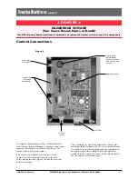
Страница 5: ...LTAGE Can Cause Severe Injury or Death Turn OFF all power before installation adjustment or removal of transfer switch or any of its components To R T Box To Power Panel Input Output Connectors to I O Modules Engine Start Connections Clock Program Backup Battery Remove protective strip to enable clock functions Network Connector Control Connections The terminals are clearly identified by a label o...

Страница 6: ...s the voltage See Figure 4 4 Close Source 1 circuit breaker NOTE The controller will illuminate Source 1 Available LED if proper voltage is sensed 5 Verify the phase to phase voltages at the Normal line terminals 6 Close the Source 2 circuit breaker 7 Start the generator engine DANGER HAZARDOUS VOLTAGE Can Cause Severe Injury or Death Turn OFF all power before installation adjustment or removal of...

Страница 7: ...losure MX150 Figure 5 LCD and keypad Initial Energization cont d After all options and accessories are checked and veri fied follow these steps to set up the ATS Refer to MX150 display Figure 5 The annunciation LEDs illuminate to indicate 1 source availability 2 ATS position and 3 MX150 control function timing 1 Unlock the enclosure 2 Open the enclosure 3 Place the Disconnect Switch in the Inhibit...

Страница 8: ...twork interface ZNET input output optional B LCD and Keypad located on the exterior of the door see figure 7 1 User accessibility to the following a LED indication of source availability b LED indication of transfer switch position c LCD screen indicates 1 timer count down numeric 2 event reporting text d Keypad provides user interface to in conjunction with LCD screen 1 Setting sensors and timers...

Страница 9: ...depending on which screen is being displayed 2 or the word on the LCD above the key The word above the key changes depending on which screen is being displayed 3 or the word on the LCD above the key The word above the key changes depending on which screen is being displayed 4 or the word on the LCD above the key The word above the key changes depending on which screen is being displayed CurrentTim...

Страница 10: ... to Source 2 Frequency Fail Factory Default 90 This adjustment determines the low frequency threshold Adjust via the SET menu Range is 88 to 98 in 1 increments see page 18 Fail must be a minimum of 2 below Restore setting Once satisfied the W timer will begin timing to transfer to Source 2 6 Test Switch Momentary A3 Auxiliary Contact Closed when the switch is in Source 2 position A4 Auxiliary Cont...

Страница 11: ... In the event that the Sources do not come within 7 electrical degrees of each other within 60 seconds the unit will display the message SYNCH CHECKING and will allow the user to BYPASS If the BYPASS button is pressed the unit will display the message WARNING MAY CAUSE DAMAGE TO THE LOAD Pressing XFR will actually bypass the R50 Since R50 is a passive device the length of time it takes to reach Sy...

Страница 12: ...nfigured by end user for 1 7 14 28 365 day cycle Standard Features MEXEG Option Pkg VI Voltage Imbalance Three Phase For a three phase source this feature monitors phase voltage ratios based on a selected range within a selected time window Should any phase fall below the selected lower window limit or exceed the selected higher window limit within the selected time frame the controller initiates ...

Страница 13: ...cy M82 Digital Meter w Display of Amps Watts Volts Frequency KVA KVAR PF etc M83A Digital Meter w Diplay of Amps Watts Volts Frequency KVA KVAR PF etc Plus THD capability w Modbus T3 W3 Elevator Pre Signal Auxiliary Contacts Open 0 60 seconds prior to transfer to either direction re closes after transfer Factory default 20 seconds UMD Universal Motor Load Disconnect Circuit Auxiliary Contact opens...

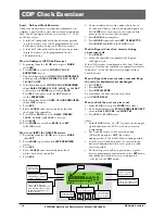
Страница 14: ...ttery will last 5 years and provides power to retain clock function only Controller functions without battery Load No Load One event Exerciser with adjustable Timer Exercise duration can be set between 5 and 60 minutes in 1 minute increments Can be configured to run every 1 7 14 or 28 days Factory default is 20 minutes How to CONFIGURE CFG and Set SET the Timer Exerciser 1 Beginning from the S1 OK...

Страница 15: ...ol Down Timer Exercise will be repeated at the same time as initiated on every 1 7 14 or 28 days according to the selection made in the Configure CFG menu How to Bypass Cancel an exercise during an exercise cycle 1 Press BPASS 2 Allow the controller to complete the Engine cool down cycle If the CDT Exerciser is Factory configured for a No Load Exerciser Or allow the controller to complete retransf...

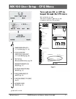
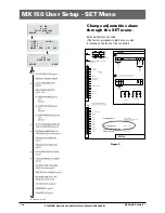
Страница 16: ... 8 Press UP or DOWN to select DAILY WEEKLY 14 DAY 28 DAY or 365 DAY as desired 9 Press SAVE 10 Press MORE repeatedly to BACK then ESC to S1 OK screen How to set SET the DAILY Exerciser 1 Beginning from the S1 OK screen press MORE then SET 2 Press MORE repeatedly until SET EXERCISER screen 3 Press SEL 4 Enter ACCESS code located on white label on the back of the controller 5 Press SEL 6 Cursor is i...

Страница 17: ...LEV PRE OUT ALARM OUT MOTOR DISC OUT INHIB S1 INHIB S2 1 2 3 4 5 6 7 8 9 10 11 12 13 14 J4 12v Output Source LN OUT L4 OUT L3 OUT L2 OUT L1 OUT YN IN YE IN TSNL IN Q2 TSL IN S12 IN Lithium Battery Exerciser Battery Replacement K 4100 BR2032 Service Life 10 Years During normal operation User Access Code Default 121212 PRODUCT INFORMATION www geindustrial com 24 Hour Service 773 299 6600 MX150 A2 A1...

Страница 18: ...T ELEV PRE OUT ALARM OUT MOTOR DISC OUT INHIB S1 INHIB S2 1 2 3 4 5 6 7 8 9 10 11 12 13 14 J4 12v Output Source LN OUT L4 OUT L3 OUT L2 OUT L1 OUT YN IN YE IN TSNL IN Q2 TSL IN S12 IN Lithium Battery Exerciser Battery Replacement K 4100 BR2032 Service Life 10 Years During normal operation User Access Code Default 121212 PRODUCT INFORMATION www geindustrial com 24 Hour Service 773 299 6600 MX150 A2...

Страница 19: ...3 4 5 6 7 8 9 10 11 12 13 14 J4 12v Output Source LN OUT L4 OUT L3 OUT L2 OUT L1 OUT YN IN YE IN TSNL IN Q2 TSL IN S12 IN Lithium Battery Exerciser Battery Replacement K 4100 BR2032 Service Life 10 Years During normal operation User Access Code Default 121212 PRODUCT INFORMATION www geindustrial com 24 Hour Service 773 299 6600 MX150 A2 A1 RELAY 14 11 12 Customer Input Voltage COM J2 3 N O N C To ...

Страница 20: ...roper operation See National Electric Code articles 700 and 701 ATS Testing Start generator and verify proper voltage frequency and phase sequence match to Source 1 Shut down gen set and place in Auto Complete the visual inspection of the transfer switch and close the cabinet door Initiate the test by pressing the TEST button on the LCD keypad The controller will then prompt for your access code A...

Страница 21: ...hen Source 2 voltage and frequency reach the preset Restore values the time delay to open Source 1 timer W begins its timing cycle to ensure voltage and frequency stabilization before re transfer A manual pushbutton BYPASS is provided to bypass the W time delay if desired After the W time delay the MX controller initiates a transfer signal through the SCR NO to operate the main transfer operator T...

Страница 22: ...e Controls Power Supply CPS This is accomplished by the Controls Power Supply CPS This method of switching operator voltage and applying power and sensing voltage to the printed circuit board isolates the MX150 from the line voltage further protecting the controller from harmful line transients Primary CPS CPS Voltage Assembly Board at 50 60 Hz Part No No 120V 50P 1224 50P 1200 208 220V 50P 1225 5...

Страница 23: ...07 XE2 SOURCE 2 3 PHASE SENSING TRANSFORMER 808 908 C V SCR N CONTROL VOLTAGE SOURCE 1 JC C V SCR N 801 JC JC JC C V SCR E C V SCR N CONTROL VOLTAGE SOURCE 1 C V SCR E CONTROL VOLTAGE SOURCE 2 C V SCR EO CONTROL VOLTAGE OPEN SOURCE 2 C V SCR NO CONTROL VOLTAGE OPEN SOURCE 1 SCR NO JC 908 JC C V SCR E C V 901 JC JC 908 808 JC SCR EO C V JC JC 801 JC SCR N C V GND 907 903 902 801 901 807 804 803 904...

Страница 24: ...age or frequency not within acceptable parameters Power supply connector unplugged Check utility and utility breakers Plug in connector General Troubleshooting The following troubleshooting guide is used to recognize and determine basic faults When using this guide it will ask several questions about the condition of the switch This guide will then list an order of the possible faults You will the...

Страница 25: ...included in a 3 5 year service cycle The battery maintains the exerceser memory only and does not otherwise affect the operation Testing A manual operator handle is provided with the transfer switch for maintenance purposes only Manual operation of the switch must be checked before it is operated electrically Both power sources must be disconnected before manual operation of the switch Insert the ...

Страница 26: ...th Controls ZTG ZTGD Operation and Maintenance Manual 70R 1000D Power Panel and Replacement Parts Standard Transition 40 to 260 Amps Solenoid Type T1 T2 T3 TN E1 E2 E3 EN N 1 N 2 N 3 N N SCR N SCR E CN CE SCN SCE ...

Страница 27: ...trols 27 ZTG ZTGD Operation and Maintenance Manual 70R 1000D Power Panel and Replacement Parts cont d Standard Transition 400 to 600 Amps Molded Type T1 T2 T3 TN E1 E2 E3 EN SN A4 SCR N SE A3 CN CE N1 N2 N3 NN SCR E ...

Страница 28: ...lts Poles 2 3 4 K 2147 208 240 380 416 3 K 2168 480 3 4 K 2157 3 4 K 2187 575 600 Main Operating Coils SN CCN Cutout Switch 23P 1333 23P 1333 SE CCE Cutout Switch 23P 1327 23P 1452 A3 Emergency Position Auxiliary Contact Qty 1 23P 1327 Qty 2 23P 1328 Qty 3 23P 1334 Qty 4 23P 1336 A4 Normal Position Auxiliary Contact Qty 1 23P 1333 Qty 2 23P 1334 Qty 3 23P 1328 Qty 4 23P 1330 DS Disconnect Switch o...

Страница 29: ...K 2123F 240 4 K 2127F K 2127F K 2127F 3 K 2125F K 2125F K 2125F 208 4 K 2128F K 2128F K 2128F 3 K 2153F K 2153F K 2153F 575 600 4 K 2154F K 2154F K 2154F 3 K 2120F K 2120F K 2120F 480 4 K 2130F K 2130F K 2130F Main Operating Coils 416 3 K 2126F K 2126F K 2126F SN CCN Cutout Switch 23P 1352 23P 1352 SE CCE Cutout Switch 23P 1356 23P 1356 A3 Emergency Position Auxiliary Contact Qty 1 23P 1356 Qty 2 ...

Страница 30: ... 2591 S 2591 N 1 2 3 N E 1 2 3 N T 1 2 3 N Wire Size 4 600 MCM 4 600 MCM Coil Volts 120 K 2245B 208 240 K 2246B 380 415 K 2247B 440 480 K 2248B CN CE Solenoid 575 600 K 2249B Handle Manual E3054 Handle Grip L 3078 A3 A4 Auxiliary Contacts L 3078 SNO SEO Coil Cutout Switch E 3521 SCR N SCR E SCR PS 8895 600 S 1393F 2 600 MCM MAIN SECONDARY 58P 1106 58P 1107 58P 1108 58P 1109 58P 1110 575 600 K 2249...

Страница 31: ...00D Power Panel and Replacement Parts cont d Delayed Transition 800 to 1200 Amps SCR N SCR E SCR PS 8896 SCR NO SCR EO MOVABLE CONTACT ARC GRID STATIONARY CONTACT SE1 2 3 4 SN1 2 3 4 A3 TERMINAL BLOCKS A4 TERMINAL BLOCKS T1 T2 T3 N1 N2 N3 SCR N E1 E2 E3 SCR NO SCR EO SCR E ...

Страница 32: ...tage System Volts Ph Wire Coil VDC Pole Solenoid Part No 120 1 2 120 2 S P O S P O S P O 120 240 1 3 240 2 3 K 2151 K 2151 K 2151 240 3 3 240 3 K 2151 K 2151 K 2151 120 208 3 4 208 3 4 K 2151 K 2151 K 2151 480 3 3 480 3 K 2160 K 2160 K 2160 575 3 3 575 600 3 S P O S P O S P O 277 480 3 4 480 3 4 K 2160 K 2160 K 2160 120 240 2 4 240 4 K 2151 K 2151 K 2151 240 416 3 4 416 3 Consult Factory Operating...

Страница 33: ... GE Zenith Controls 33 ZTG ZTGD Operation and Maintenance Manual 70R 1000D ...

Страница 34: ... 34 GE Zenith Controls ZTG ZTGD Operation and Maintenance Manual 70R 1000D ...

Страница 35: ... GE Zenith Controls 35 ZTG ZTGD Operation and Maintenance Manual 70R 1000D ...

Страница 36: ...A Product of GE Industrial Systems General Electric Company 830 West 40th Street Chicago IL 60609 USA 773 299 6600 Fax 773 247 7805 www geindustrial com GE Zenith Controls ...

Отзывы: