background image

5

Maintenance

Test the sensor at least once a year to verify proper range and 
coverage. Instruct the end user to put the sensor in walk test 
mode and walk through the end of the coverage pattern to verify 
proper detection.

Battery replacement

When you replace the batteries, observe proper polarity (as 
shown in the battery compartment) to avoid damage to the 
sensor. 

To replace the batteries, do the following:
1.

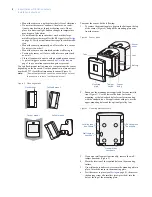
Remove the sensor from the mounting plate and slide the 
cover off the sensor to reveal the battery compartment.

2.

Remove the batteries and replace with the new ones. Be 
sure to observe polarity. As you look at the battery compart-
ment, on the left side the positive end is down and on the 
right side the positive end is up (

Figure 4

 on page 2).

3.

Wait at least three minutes after installing the batteries 
before you activate walk test mode.

Troubleshooting

If the system doesn’t respond correctly when the sensor is acti-
vated, follow these guidelines:

• Check sensor programming (refer to the panel’s program-

ming instructions) and reprogram the sensor if necessary. 

• Move the sensor to another location and test for correct 

response.

To relocate the sensor, do the following:
1.

Test the sensor a few inches from the original position.

2.

Increase the distance and retest until you find an acceptable 
location.

3.

Mount the sensor in the new location.

If no location is acceptable, do the following:
1.

Test a known good sensor at the same location.

2.

If the system does not respond, avoid mounting a sensor at 
that location.

3.

If the replacement sensor functions, return the problem 
sensor for repair.

CAUTION:  

Replace only with two AA 1.5 V alkaline 
batteries. Dispose of used batteries 
according to the manufacturer’s 
instructions and local government 
authorities.

Содержание 60-639-95R

Страница 1: ...tivated tamper an optional wall activated tamper is provided supervisory signal transmitted every 64 minutes to the control panel sensor low battery reports trouble to the control panel and field selectable sensitivity options Indoor sensor installation Use the following installation guidelines If possible mount the sensor within 100 ft 30 5 m of the panel While the transmitter may have a range of...

Страница 2: ...ote The wall tamper switch cannot be used when you mount the sensor in a corner or on the swivel mount Figure 3 Mounting options To mount the sensor do the following 1 To remove the mounting plate depress the button on the top of the sensor Figure 4 and pull the mounting plate away from the sensor Figure 4 Sensor parts 2 Punch out the mounting holes applicable for your installa tion Figure 5 Use t...

Страница 3: ...o flush mount or corner mount the sensor with the back of the sensor parallel to the walls Do not use the inclined mount position because this will tilt the sensor s field of view downward Position the sensor so that is has a clear line of sight across the protected room Sensitivity settings The sensor is set to standard sensitivity at the factory This sensi tivity is preferred for most applicatio...

Страница 4: ... Testing Testing the sensor includes a walk test an environment test and a final test with the control panel Walk test Walk test the unit from both directions to determine the pattern boundaries The edge of the coverage pattern is determined by the first flash of the LED This may change slightly depending on the sensitivity setting To walk test the sensor do the following 1 Remove the sensor from ...

Страница 5: ...utes after installing the batteries before you activate walk test mode Troubleshooting If the system doesn t respond correctly when the sensor is acti vated follow these guidelines Check sensor programming refer to the panel s program ming instructions and reprogram the sensor if necessary Move the sensor to another location and test for correct response To relocate the sensor do the following 1 T...

Страница 6: ...r sensor Outdoor sensor 32 to 120 F 0 to 49 C 10 to 120 F 12 to 49 C Storage temperature 30 to 140 F 34 to 60 C Maximum relative humidity 90 relative humidity noncondensing Dimensions L x W x H 2 9 x 2 4 x 1 9 in 74 x 61 x 48 mm Austria Italy Denmark Netherlands France Portugal Germany Spain Ireland Sweden Manufacturers Declaration of Conformity Product identification Model type 60 639 43 EUR and ...

Отзывы: