background image

CamPlus 2 Vandal Resistant Dome IP Camera

Installation Manual

8

Installing the camera

To install the camera, do the following:

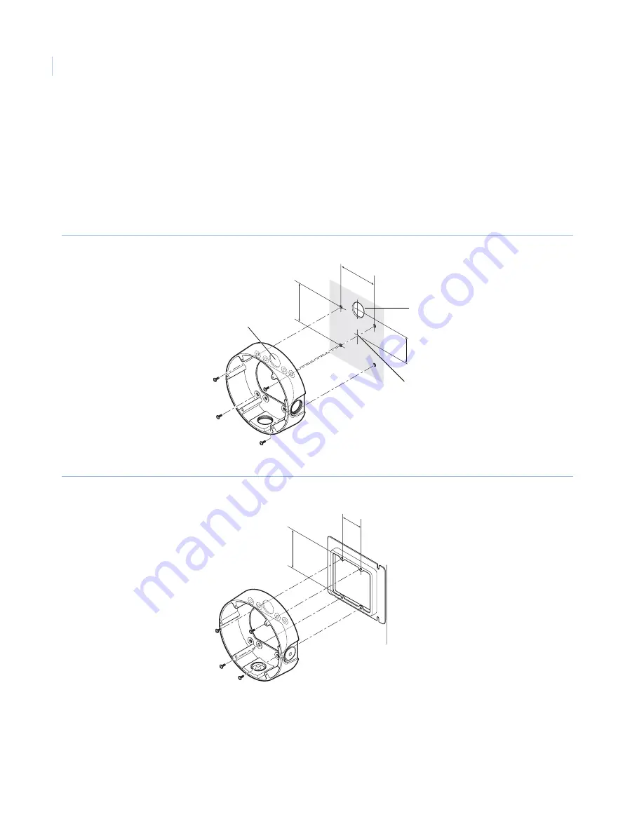
1. Install the mounting bracket. 

Fix the mounting bracket directly into the ceiling or wall (

Figure 4

) or into a double-gang box 

(

Figure 5

) using four fasteners appropriate to the installation. (Note that fasteners for installation are 

not provided.) 

Figure 4. Installing the mounting bracket

Figure 5.  Installing the double-gang box

Note:  

When installing the camera outdoors, waterproof the screws and screw holes. 

Cable pass-through 
hole

Cable pass-through 
hole

85 mm

85 mm

Center of metal 

installation bracket

Installation screws x 4

51 mm

Installation screws x 4

84 mm

46 mm

Содержание CamPlus 2 GEC-IP2VD-DN

Страница 1: ...CamPlus 2 Vandal Resistant Dome IP Camera Installation Manual GE Security ...

Страница 2: ...ded use Use this product only for the purpose it was designed for refer to the data sheet and user documentation For the latest product information contact your local supplier or visit us online at www gesecurity com FCC compliance This equipment has been tested and found to comply with the limits for a Class A digital device pursuant to part 15 of the FCC rules These limits are designed to provid...

Страница 3: ...ore installation 6 Installing the camera 8 Connecting the Cables 12 Connections 15 Adjusting the camera 16 Install the camera enclosure 18 Handling SD memory cards 19 Inserting a memory card 19 Removing a memory card 20 Heater module 21 Installing the heater module 21 Installing the software 23 Troubleshooting 26 Contacting us 27 Online resources 27 ...

Страница 4: ...CamPlus 2 Vandal Resistant Dome IP Camera Installation Manual iv ...

Страница 5: ...7 for instructions on accessing our online publication library Note A qualified service person complying with all applicable codes should perform all required hardware installation The following conventions are used in this document Safety terms and symbols These terms may appear in this manual Related documentation The CD ROM contains the CamPlus 2 Vandal Resistant Dome IP Camera User Manual Refe...

Страница 6: ...1 CamPlus 2 Vandal Resistant Dome IP Camera Product contents The CamPlus 2 Vandal Resistant Dome IP Camera system consists of the following CamPlus 2 Vandal Resistant Dome IP Camera CamPlus 2 Vandal Resistant Dome IP Camera Installation Manual CD ROM with Easy IP Setup software CamPlus 2 IP Viewer software and CamPlus 2 Vandal Resistant Dome IP Camera User Manual MAC Address code sheets Mounting B...

Страница 7: ... 32 bit When supported OS is Windows 2000 Professional SP4 Internet Explorer 6 0 SP1 Web Browser Internet Explorer 6 0 SP2 Internet Explorer 7 0 CD ROM drive Required to read the operating instructions and use the software on the CD ROM DirectX 9 0c or later Adobe Reader Required to read the operating instructions Note When using a PC that does not meet the above requirements displaying images may...

Страница 8: ...ome IP Camera Installation Manual 4 Components Figure 2 Camera components Enclosure Mounting bracket Focus lever Zoom lever Tilt adjustment Network cable Tilt lock screw Power cable Alarm I O cable Panning lock screw Panning table ...

Страница 9: ...5 Figure 3 Additional camera components Monitor output jack Heater connector LED on off switch SD memory card error LED SD memory card slot ABF button ABF LED Access LED Link LED INIT button ...

Страница 10: ... About White Balance White balance may not be correctly obtained in the following instances When capturing subjects having extremely little white or subjects close to a single color When capturing images outdoors at dawn or dusk or in low illumination When capturing images having extremely different color temperatures e g in color lighting About Static Electricity Removal Before installing the cam...

Страница 11: ... or radio transmission antennas or near strong electric or magnetic fields e g motors or transformers In this case setup a specialized thin conduit and pass the cable through it Power Supply by PoE Use a PoE compatible IEEE802 3afcompliant hub or power supply unit ...

Страница 12: ...ng box Figure 5 using four fasteners appropriate to the installation Note that fasteners for installation are not provided Figure 4 Installing the mounting bracket Figure 5 Installing the double gang box Note When installing the camera outdoors waterproof the screws and screw holes Cablepass through hole Cable pass through hole 85 mm 85 mm Center of metal installation bracket Installation screws x...

Страница 13: ...er Note When replacing the dome cover sold separately refer to the Installation Instructions provided with the dome cover 3 Remove the transportation screw Figure 7 Figure 7 Removing the transportation screw 4 Connect the power cable and the video output cable See Waterproofing cable joints on page 13 Transportation screw ...

Страница 14: ...ounting bracket and the indented part on the camera to fix the position of the camera Tighten the screws used for mounting the camera Figure 8 Installing the camera on the mounting bracket CAUTION Firmly tighten the installation screws to maintain a weatherproof seal Camera body Mounting bracket 2 positioning parts left and right 2 positioning parts left and right Installation screws Installation ...

Страница 15: ...SD memory card insert the card before going on to the next phase of the installation process See Handling SD memory cards on page 19 When installing the optional heater module install it before going on to the next phase of the installation process See Heater module on page 21 Cable Camera Double gang box Mounting bracket ...

Страница 16: ... describes the cables Figure 10 Cabling Table 1 3 pin power cable provided Cable 24 V AC 12 V DC Blue Neutral Neutral Minus Green yellow GND Connect to ground Brown Live Live Plus Network cable RJ 45 female female conversion connector included Power cord 24 V AC 12 V DC Alarm I O cable 4 pin alarm cable included 3 pinpowercable included ...

Страница 17: ...nnector 3 Wrap each connector with butyl rubber tape Figure 11 Figure 11 Waterproofing cabling Waterproof the connections of the 3 pin power cable provided and the 4 pin alarm cable provided to their external devices in the same way Stretch the tape to about twice its length and wrap it around the cable Figure 12 Sufficient waterproofing performance cannot be obtained unless the tape is sufficient...

Страница 18: ...bottom side of the camera Draw out the cable to the side of the mounting fixture Figure 14 Figure 14 Bottom side of camera facing down When installing the camera on a wall install it so that the water drain groove is facing down Figure 15 Do not block the water drain groove Blocking the water drain groove will prevent the dehumidifying element at the rear of the camera from functioning Water that ...

Страница 19: ... during installation or servicing It is not intended for recording or monitoring images Text displayed on the monitor screen may be clipped depending on the monitor you are using The switching hub or router used must be 10BASE T 100BASE TX compatible A separate power supply is required for each network camera Separate power supplies are not required when a PoE compatible hub is used Ethernet cable...

Страница 20: ... the camera angle while repeating the fine adjustments in the following a b and c steps Figure 18 Figure 18 Pan and tilt controls a Loosen the pan lock screw and rotate the camera horizontally to adjust pan b Loosen the 2 tilt lock screws and rotate the camera vertically to adjust tilt c Turn the tilt adjustment seat to adjust the screen tilt d When the camera angle is determined tighten the pan l...

Страница 21: ...atisfaction 5 Press the ABF button The ABF LED Figure 3 on page 5 lights the focus position is displayed at the bottom of the adjustment monitor screen Figure 20 and the back focus is automatically adjusted Figure 20 Focus position When connected to a network the camera can be operated and checked from the CamPlus 2 IP Viewer software Note Pressing and quickly releasing the ABF button immediately ...

Страница 22: ... at both the near infra red area and the visible light area when adjusting method is set to AUTO or PRESET How to Use the Varifocal Lens and Zoom Lens Before adjustment reset the back focus position and return the CS mount to its default position Install the camera enclosure To install the enclosure do the following 1 Install the enclosure Align the mark on the side of the enclosure with the line ...

Страница 23: ...card To insert a memory card do the following 1 Insert the SD memory card into the SD memory card slot Figure 21 Figure 21 Inserting a memory card 2 Press the SD memory card in as far as possible until it clicks into place Figure 22 Figure 22 Clicking the memory card into place CAUTION Turn the camera off before inserting or removing an SD memory card ...

Страница 24: ...IP Camera Installation Manual 20 Removing a memory card To remove an SD memory card press it in as far as possible again You will hear it click and it will rise up Remove the SD memory card Figure 23 Figure 23 Removing the memory card ...

Страница 25: ... while it is turned on Disconnect the connector from the camera and wait for the heater to cool down before removing it When the heater module is installed and used in environments of 10ºC 14ºF or below normal images may not be obtained immediately after the camera is started up The camera may take up to two or more hours to warm up before producing a normal image Installing the heater module To i...

Страница 26: ...module cable to the connector on the camera body CAUTION After installing the heater module pull the cable through so that it is not pinched while installing the enclosure While pulling the cable through make sure that it does not become entangled with the movable parts inside the camera ...

Страница 27: ...hen the network settings cannot be configured using the Easy IP Setup software set up the cameras and PC individually in the Network setup page of the viewer software When Windows XP SP2 is used an important alert screen regarding security may be displayed when the Easy IP Setup software is started up If this happens click the Unblock U button To enhance security the Easy IP Setup software turns o...

Страница 28: ...up software by double clicking EasyIpSetup exe on the CD ROM 2 Click the MAC address IP address of the camera to set up and click the IP setting button Figure 25 Note When a DHCP server is in use you can check the IP address assigned to the camera by clicking the Refresh button in the Easy IP Setup software Figure 25 Easy IP Setup software ...

Страница 29: ...k settings Note It takes about 30 seconds for settings on the camera to take affect after clicking the Apply button The settings will be invalid if the camera is turned off or the Ethernet cable is disconnected before the settings are applied If this happens change the settings again If a firewall including software is installed allow access of all UDP ports ...

Страница 30: ...questing service check the following items Camera does not turn on AC DC power supply Is the power firmly connected to the power outlet Make sure that it is connected PoE power supply Is the network cable connected to a PoE compatible power supply unit by an Ethernet Category 5 cable Make sure that it is connected Some power supply units that can connect multiple PoE terminal devices are not suppl...

Страница 31: ...ce and technical support From the Customer Support menu select Customer Service or Technical Application Select the appropriate product category for the contact information or use the menu to select a location outside the US Table 2 Technical support North America Latin America T 888 GE Security 888 437 3287 Toll free in the US Puerto Rico and Canada 503 885 5700 outside the toll free area F 888 3...

Страница 32: ...CamPlus 2 Vandal Resistant Dome IP Camera Installation Manual 28 ...

Отзывы: