


CamPlus 2 Traditional Box IP Camera
Installation Manual
10
SD memory cards
Follow these SD memory card guidelines:
•
To prevent malfunction or damage to card data, turn the camera off before you insert an SD card.
•
Use the camera to format SD memory cards. If you use an unformatted SD card or an SD card
formatted with another device, the camera may not work.
•
Use Panasonic SD memory cards. Other cards have not been tested and may affect your camera’s
performance.
•
To keep your personal information secure, remove the SD memory card from the camera when sending
your camera for repair.
•
Replace the SD memory card when you have periodic maintenance done on the camera.
Note:
Performance with this camera has been checked using Panasonic SD memory cards up to 2 GB. If another SD memory
card is used, this camera may not operate properly. The SD High Capacity (SDHC) card is not compatible with this camera, and
may cause the camera to not start up.
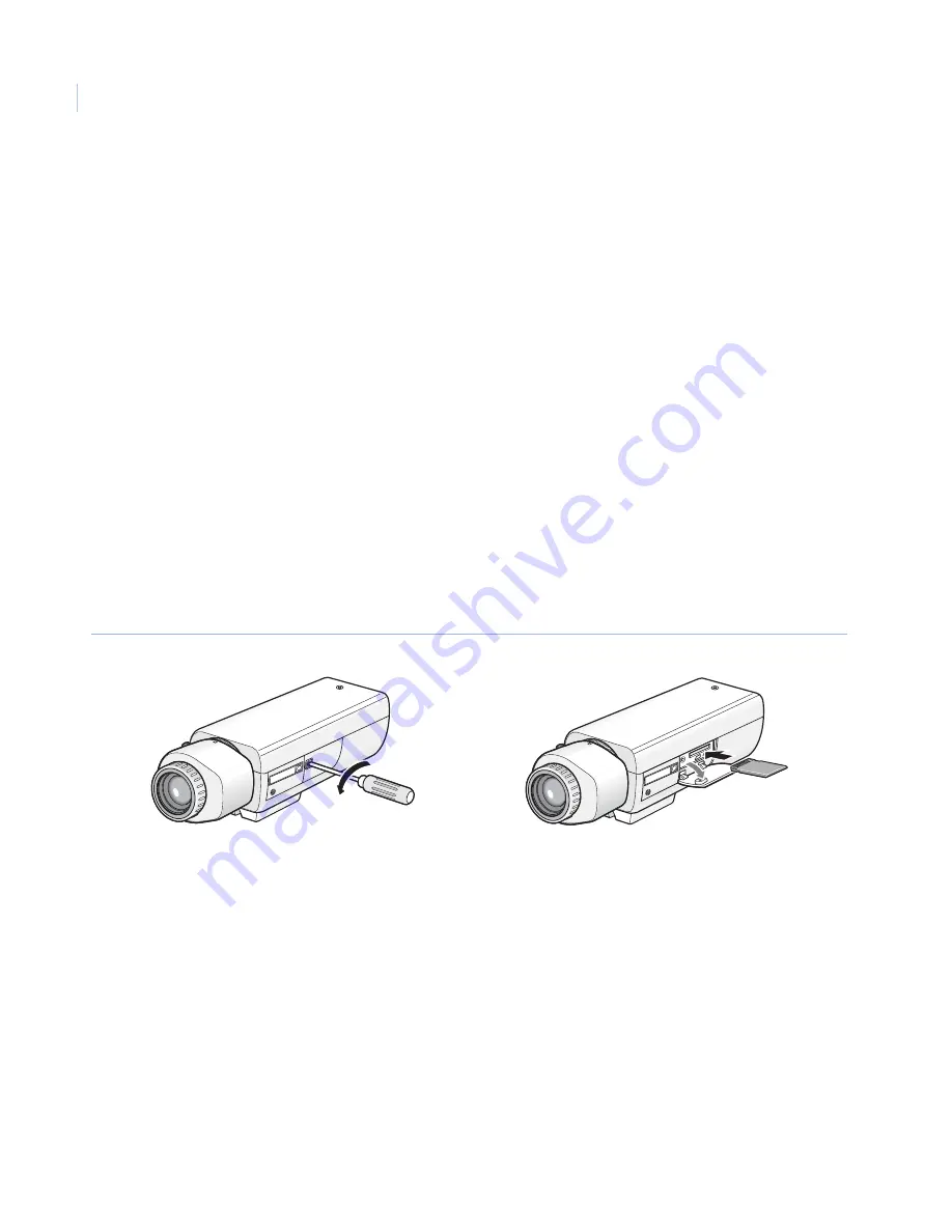
Insert the SD memory card
To insert the SD memory card, see
Figure 12
and do the following:
1. Turn the camera off.
2. Loosen the screw of the SD memory card slot cover.
Figure 12. Inserting the SD memory card
3. Open the SD memory card slot cover.
4. Insert an SD memory card (backside up) into the SD memory card slot.
5. Close the SD memory card slot cover and fasten the screw.
6. Start the CamPlus 2 IP Viewer software, and on the
Setup
menu
Basic setup
tab, select
Use
for
About
SD memory card
. Refer to the
User Manual
for further instructions.
LOCK
LOCK


