GE Medical Systems LOGIQ 500 Скачать руководство пользователя страница 25

Quick Start 19

LOGIQ

t

 500 Quick Start Guide 

2276613–100  Rev. 0

Color Flow Mode (CFM) Controls (cont’d)

Acoustic output affects the transmit power for both B-Mode and CFM signals.

TGC and B/M Gain function only on the B-Mode image displayed.

The Dual Format keys work the same as in dual B-Mode, but both B-Mode and CFM are displayed on the left and right
sides of the screen.

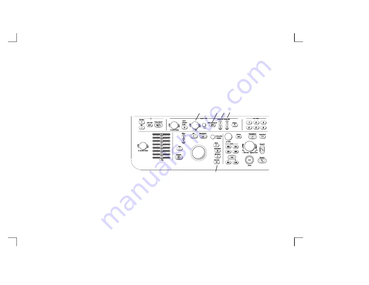
The keyboard controls that effect CFM are as follows:

1.

Color Doppler Gain—Adjusted overall
received echo gain for CFM.  To
increase/decrease, turn the control
clockwise/counterclockwise.

2.

CFM/Spectrum Invert—Inverts Color
Flow Map assignments.

3.

Velocity Scale—Adjusts velocity scale to
accommodate faster/slower blood flow
velocities.  To increase/decrease, press
the top/bottom of the Velocity Scale
rocker switch.

4.

Baseline Shift—Minimize aliasing by assigning more of the overall displayed velocity scale to forward or reverse flow.
To shift the baseline up/down, press the top/bottom of the Baseline Shift rocker switch.

5.

Color Flow Window Size (Scan Area)—Used to assign trackball control to adjust size/position of the CFM window.

1

5

2

3 4

"

y

A

"

y

A

Содержание LOGIQ 500

Страница 1: ... TiP TM LOGIQ 500 Quick Start Guide 2276613 100 A Training in Partnership Program ...

Страница 2: ...This page left blank intentionally ...

Страница 3: ... ...

Страница 4: ...Guide is a reference for LOGIQ 500 PRO Series It applies to all versions of 6 0 software for the LOGIQ 500 GE Medical Systems GE Medical Systems Telex 3797371 P O Box 414 Milwaukee Wisconsin 53201 U S A Asia Pacific Latin America North America GE Ultrascall Tel 49 0 212 28 02 208 Deutschland GmbH Co KG Beethovenstraße 239 Postfach 11 05 60 D 42655 Solingen GERMANY ...

Страница 5: ... History A LOGIQ 500 Quick Start Guide 2276613 100 Rev 0 REV DATE REASON FOR CHANGE 0 July 10 2000 Initial Release TiP Cover Page N A Title Page 0 Revision History A and B 0 Quick Start 1 thru Quick Start 40 0 ...

Страница 6: ...Revision History B LOGIQ 500 Quick Start Guide 2276613 100 Rev 0 ...

Страница 7: ...em safely The Quick Start Guide takes the user from system familiarization through power on patient data entry exam category preset selection scan modes adjustments basic measurements report pages recording images and power off The LOGIQ 500 manuals are written for users who are familiar with basic ultrasound principals and techniques They do not include sonography training or clinical procedures ...

Страница 8: ...with the standard configuration while other features are options to the standard console 1 VCR Microphone 2 Probe Holder 3 MOD Drive 4 Physio Panel 5 Probe Connectors 3 ports 6 Air Filter 7 Power Supply Filter 8 On Off Switch 9 B W Page Printer 10 Keyboard 11 Keyboard Task Light 12 Task Light Switch optional feature or accessory 1 3 4 5 8 7 6 10 11 12 2 9 ...

Страница 9: ...2276613 100 Rev 0 Back View 1 Circuit Breaker 2 Air Filter 3 Cable Access 4 Peripheral Cable Access Door 5 Handle for Pushing 6 Monitor Arm Swivel Lock 7 Color Monitor Optional Freeze Record Foot Switch ON OFF 1 0 ON 1 2 3 4 5 6 7 Freeze Record ...

Страница 10: ...ower switch is turned off S Unwrap the power cable Make sure to allow sufficient slack in the cable so that the plug is not pulled out of the wall if the system is moved slightly S Push the power plug securely into the wall outlet To power on the system ensure that the Circuit Breaker located on the back of the power supply near the bottom of the unit is turned on Press the Power On Power Off Stan...

Страница 11: ...uick Start Guide 2276613 100 Rev 0 Power On cont d During power up the screen display changes as the system runs its self diagnostics Start of diagnostic End of diagnostic Version X XX Version X XX Version X XX XXXXXXX XXXXXXX ...

Страница 12: ... been arranged according to function and usage This helps minimize operator movement while scanning 1 Alphanumeric Keys 2 New Patient 3 Probe Select 4 Soft Menu Controls 5 Doppler and CFM 6 User Define 7 Mode Display and Record 8 Measurements Annotations 9 TGC and Acoustic Output 10 VCR yA yA 1 2 3 4 5 6 7 9 8 10 ...

Страница 13: ... the top level menu page selections The far left side top menu is the default selection and its sub menus are automatically displayed The Sub Menu Select rocker switch cycles to the next or previous A sub menu page The Sub Menu rocker switches allow for the increase decrease of a parameter value or enabling disabling of a parameter Sub Menu Select Top Menu Select SUB MENU Current Available TOP MEN...

Страница 14: ...le CWD key is used to activate the dedicated continuous wave Doppler CWD probe The active probe key will be brightly lit Probe Ports All imaging probes can be plugged into any of the three probe ports The CWD probes can be plugged into the Single CWD port which is located above Probe Port Position 3 NOTE Ensure that the probe port is deactivated and the image is frozen before disconnecting the pro...

Страница 15: ...nu appears Ensure that the Blue Shift key is not active Use the Trackball to move the highlight cursor to the Exam Category Selection line Enter the desired exam number and fill in the appropriate patient data Highlight EXIT and press Return or press New Patient again when the patient entry menu data has been completed The system takes a few seconds to load new exam category parameters and calibra...

Страница 16: ...ev 0 Application Presets Select the exam category application preset that best describes the desired study to be performed from the factory default preset selections displayed on the Soft Menu Select the desired probe Newborn Tech Diff Fetal Heart General OB ...

Страница 17: ...modes B Mode Pulsed Doppler Color Flow Mode M Mode or Continuous Wave Doppler Mode CWD Mode is available for sector probe only If the dual display mode split screen is desired the L and R keys activate the Left or Right displayed image Scan the desired anatomy Change modes as desired Use the mode controls to adjust the image as necessary ...

Страница 18: ...Automatic Tissue Optimization optimizes the image based upon a specified Region of Interest ROI or anatomy within the display ATO On Off Highlighted when the ATO map is active on the image toggle on and off to display that same ATO map again Frame Average Averages previous frames of image data with the current frame Imaging Freq Allows more echoes to pass through Image Softner Adjust for the amoun...

Страница 19: ...ay scale displayed Biopsy Zone Enables the electronic guidezone s available for the active probe Image Rotate Rotates the single real time or zoomed B Mode image in 90 increments Rejectn Allows for the elimination of low level echoes from the display B Edge Enhance Brings out subtle tissue differences and boundaries by enhancing the gray scale differences corresponding to the edges of structures T...

Страница 20: ...c Output Allows for varying the power output of the transmitted sound wave 2 TGC Balances the image so brightness is consistent throughout the image Move the slide pot to the right to increase or the left to decrease 3 Scan Area Used to assign trackball control to adjust size position B Mode sector display CFM window and horizontal size position of the real time zoom window ...

Страница 21: ...t Right split screen display 6 Reverse The GE logo at the top of the sector wedge corresponds to the orientation mark on the probe body When Reverse is active the image flips and the GE logo switches to correspond to the probe mark 7 B M Gain Controls the gain of the displayed echoes To increase decrease turn the control clockwise counterclockwise 8 Angle Controls the gain in B M and CFM B M Mode ...

Страница 22: ...ynamic Range 3 Increase Frame Average 4 Increase Edge Enhance Improve Uniformity 1 Increase the number of focal zones 2 Decrease SCAN AREA SIZE 3 Adjust TGC to compensate for attenuation Cystic Imaging 1 Decrease the B M GAIN 2 Decrease Dynamic Range 3 Use SCAN AREA SIZE to reduce image width 4 Change Focus Number to increase number of focal zones 5 Optimize focal zone placement Technically Diffic...

Страница 23: ...ers out low flow velocity color Frame Average Averages color information from previous frames with the current frame Penet Penetration can be increased by lowering the operating frequency of the active probe High Resoltn Provides a quick way to maximize resolution for the CFM display Display Thrshld Gray scale level at which the overlay of color information stops Capture Displays the highest mean ...

Страница 24: ... single color to a range of velocities Tag Positn Allows for the movement of the specified color tag range throughout the gray scale displayed ACE Reduces color artifact noise Noise Blanker Reduces the random noise generated due to the increase in Color Gain Persistence Retains the largest pixel color value until a larger value is detected or preset time has elapsed MR Flow Image enhancement optio...

Страница 25: ...rall received echo gain for CFM To increase decrease turn the control clockwise counterclockwise 2 CFM Spectrum Invert Inverts Color Flow Map assignments 3 Velocity Scale Adjusts velocity scale to accommodate faster slower blood flow velocities To increase decrease press the top bottom of the Velocity Scale rocker switch 4 Baseline Shift Minimize aliasing by assigning more of the overall displayed...

Страница 26: ... SCALE 3 Increase ACOUSTIC OUTPUT 4 Switch Penet on and High Resoltn on 5 Decrease W E Cancel 6 Increase Frame Average this allows gain to increase 7 Increase Packet Size 8 Reduce SCAN AREA SIZE to smallest size reasonable 9 Optimize focal zone position Improve Frame Rate Flow Dynamics 1 Decrease color window using SCAN AREA SIZE width 2 Exit COLOR FLOW to reduce B Mode image width use SCAN AREA S...

Страница 27: ... of the vessel walls S V Length Changes the size of the sample volume gate length Not available in the CWD Soft Menu Sweep Speed Changes the speed at which the timeline updates across the display Penet Penetration can be increased by lowering the operating frequency of the active probe Not available in the CWD Soft Menu Color Allows for enabling PWD or CWD Mode image colorization Color Tag Enables...

Страница 28: ...u CFM Shrink Reduces the CFM window to specified size Not available in the CWD Soft Menu Realtim Trace Automatically traces in real time Calc Dir Choose which part of the Doppler Trace is used for automatic measurements calculations Trace Method Choose the method used to trace the Doppler waveform in real time Peak Floor Mean or Mode Dynamic Range Controls how echo intensities are converted to sha...

Страница 29: ...e decrease turn the control clockwise counterclockwise 4 Theta Angle Correction Adjusts angle correction for flow velocity calculation To adjust the angle clockwise counterclockwise relative to the probe face turn the control clockwise counterclockwise 5 CFM Spectrum Invert Inverts Doppler spectrum assignments 6 Velocity Scale Adjusts velocity scale to accommodate faster slower blood flow velociti...

Страница 30: ...equency on some applications 6 Activate B PAUSE to freeze B Mode image Scan angle is critical to Doppler sensitivity Improve Display Aesthetics 1 Activate B PAUSE to freeze B Mode image 2 Decrease GAIN 3 Increase ACOUSTIC OUTPUT 4 Use smaller sample volume size whenever possible 5 Increase decrease Dynamic Range 6 Adjust BASELINE SHIFT and VELOCITY SCALE to adjust spectral size 7 Lower Doppler Swe...

Страница 31: ...choes from the display Edge Enhance Brings out subtle tissue differences and boundaries by enhancing the gray scale differences corresponding to the edges of structures Sweep Speed Changes the speed at which the timeline updates across the display Color Allows for enabling M Mode image colorization Color Tag Enables the colorization of a specific gray scale level range Tag Positn Allows for the mo...

Страница 32: ...the displayed scan area The Dual Format keys work the same as in dual B Mode but both B Mode and M Mode are displayed on the left and right sides of the screen The keyboard controls that effect M Mode are as follows 1 B M Gain Controls the gain of the displayed timeline echoes To increase decrease turn the control clockwise counterclockwise 2 M D Cursor Assigns trackball control to the M Mode curs...

Страница 33: ... Freeze is activated rotate the Cine Scroll control to display individual image frames which were stored by the system NOTE Cine frame number 0 is the most current image The higher the Cine frame number the older the image The depth dynamic range and gain parameters displayed on the screen are valid for Cine frame number zero only ...

Страница 34: ...e position Comments may be typed in at the non blinking cursor Pressing the Comment key assigns the trackball function to controlling the cursor The Trackball and Keyboard Arrow keys are used to move the cursor to the desired position on the image When the blinking cursor is in the desired position comments may be typed in Annotations are entered in the type over not insert mode Be careful not to ...

Страница 35: ...printed on the screen during the comment function when the keys shown are pressed The Blue Shift key acts as a lock function similar to Caps Lock key Press again to exit the Blue Shift function Special Keys Language Specific Characters Special language specific characters shown in red on the keyboard can be used by activating the Red Shift key Refer to the Annotating an Image section of Chapter 6 ...

Страница 36: ...atterns A body pattern generally displayed in the lower left corner of the screen appears Cycle through the body patterns by pressing the top bottom of the Ellipse rocker switch A Probe Orientation Marker is used to illustrate the probe position This marker can be placed with the Trackball and rotated with the Zoom Size Rotation control Press Set to complete the body pattern selection Probe Orient...

Страница 37: ...ed Scan the desired anatomy and press Freeze Key Pressed MODE Key Pressed while frozen B Spectral Doppler with B M with B CFM with B Once Distance Ellipse Circle Peak Velocity Tissue Depth Distance Distance Ellipse Circle Twice Trace Circle TAMAX TAMIN TAMEAN TAMODE Time Interval Trace Circle Three Times Gray Scale Echo Level 2 Velocities Slope Time Interval Depth Difference Slope Time Interval Po...

Страница 38: ...LVIDd and LVPWs Press Measurement once Use the Trackball to move the cursor to the measurement start point Press Set to fix the measurement start point cursor and to display a second cursor Use the Trackball to move the second cursor to the measurement end point Press Set to complete the measurement and fix the Distance value displayed on the bottom part of the screen ...

Страница 39: ... the cursor to either end of the major axis of the area to measure Press Set to fix the start point cursor Use the Trackball to move the second cursor to the major axis measurement end point Press the top of the Ellipse rocker switch An ellipse having an initial circle shape appears Use the Trackball to position the ellipse as necessary and to size the measured axis Press Set to complete the ellip...

Страница 40: ...of the measurement cursors Press the top of the Ellipse rocker switch to increase the size of the minor axis Press the bottom of the Ellipse rocker switch to decrease the size of the minor axis Press Clear once to erase the ellipse and the current data measured The original cursor is displayed to restart the measurement Pressing Clear a second time exits the measurement function without completing...

Страница 41: ...oom Size Rotation knob can be used to edit the trace line Turn it clockwise or counterclockwise to erase the line bit by bit back from its current point The erase function is limited to a small portion of the most recent trace Peak Velocity Doppler Perform a peak velocity measurement for calculations such as RI PI S D Ratio Max PG and Mean PG Press Measurement The cursor with a vertical dotted lin...

Страница 42: ...rsor Use the Trackball to move the second cursor to the measurement end point Press Set to complete the measurement The time interval between the two cursors is displayed Erasing Measurements Pressing Clear or unfreezing the image erases all measurements and calculations on the display Measurements and calculations however remain on the report pages Pressing New Patient erases all measurements and...

Страница 43: ...ostic exam categories have report pages to summarize measurements and calculations performed while in that exam category These categories are Obstetrics Gynecology Cardiology and Vascular A report page can be displayed by pressing Measurement and selecting it from the measurement sub menu ...

Страница 44: ...s pressed or power is turned off Press the F1 or F2 key Image Recall selection to display the last image stored in system memory Press Top Menu Select to display a sub menu of all images stored in system memory Use the appropriate Sub Menu rocker switch to select the desired image After recall comments measurements and body patterns can be added to the image The image is then available for printin...

Страница 45: ... the system use the controls on the VCR Probe Cleaning Disinfection Probes should be cleaned and disinfected after each use The Probe Immersion Levels are provided with the probe but are also pictured in the Probes chapter of the User Manual NOTE Special instructions for the E721 and ERB7 probes are found in the Probes chapter of the User Manual F J ...

Страница 46: ...onitor The message WARNING NOW START THE POWER OFF PROCESS is also displayed at the bottom of the screen While the system is running during this power down process do NOT turn off the circuit breaker in the back of the machine and do NOT unplug the system from the wall outlet If the system has not turned off five minutes after pressing the power switch off listen for hard drive activity If there i...

Отзывы: