


5-162
B90 Low Impedance Bus Differential System
GE Multilin
5.7 INPUTS/OUTPUTS
5 SETTINGS
5
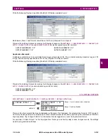
GOOSE Analogs can be compared to other GOOSE Analogs with any character string or no string.
•
GOOSE ANALOG 1 PU
: This setting specifies the per-unit base factor when using the GOOSE analog input FlexAna-
log values in other B90 features, such as FlexElements. The base factor is applied to the GOOSE analog input FlexAn-
alog quantity to normalize it to a per-unit quantity. The base units are described in the following table.
The per-unit base setting represents thousands, not single units. For example, a PU base of 1.000 is actually 1000 and
a PU base of 0.001 is 1.
When using GOOSE Analogs and PU base in FlexElements, the largest value that can be displayed in the FlexEle-
ment actual values is 2,140,000.000.
The GOOSE analog input FlexAnalog values are available for use in other B90 functions that use FlexAnalog values.
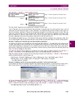
5.7.12 IEC 61850 GOOSE INTEGERS
PATH: SETTINGS
INPUTS/OUTPUTS
IEC 61850 GOOSE UINTEGERS
GOOSE UINTEGER INPUT 1(16)
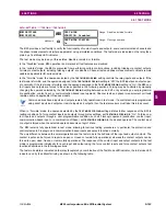
The IEC 61850 GOOSE uinteger inputs feature allows the transmission of FlexInteger values between any two UR-series
devices. The following settings are available for each GOOSE uinteger input.
•
UINTEGER 1 DEFAULT
: This setting specifies the value of the GOOSE uinteger input when the sending device is
offline and the
UINTEGER 1 DEFAULT MODE
is set to “Default Value”.This setting is stored as a 32-bit unsigned integer
number.
•
UINTEGER 1 DEFAULT MODE
: When the sending device is offline and this setting is “Last Known”, the value of the
GOOSE uinteger input remains at the last received value. When the sending device is offline and this setting value is
“Default Value”, then the value of the GOOSE uinteger input is defined by the
UINTEGER 1 DEFAULT
setting.
The GOOSE integer input FlexInteger values are available for use in other B90 functions that use FlexInteger values.
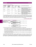
Table 5–27: GOOSE ANALOG INPUT BASE UNITS
ELEMENT
BASE UNITS
dcmA
BASE = maximum value of the
DCMA INPUT MAX
setting for the two transducers configured
under the +IN and –IN inputs.
FREQUENCY
f
BASE
= 1 Hz
PHASE ANGLE
BASE
= 360 degrees (see the UR angle referencing convention)
POWER FACTOR
PF
BASE
= 1.00
RTDs
BASE = 100°C
SOURCE CURRENT
I
BASE
= maximum nominal primary RMS value of the +IN and –IN inputs
SOURCE POWER
P
BASE
= maximum value of V
BASE
I
BASE
for the +IN and –IN inputs
SOURCE VOLTAGE
V
BASE
= maximum nominal primary RMS value of the +IN and –IN inputs
GOOSE UINTEGER
INPUT 1
UINTEGER 1
DEFAULT:
1000
Range: 0 to 429496295 in steps of 1
MESSAGE
UINTEGER 1
DEFAULT
MODE: Default Value
Range: Default Value, Last Known
Содержание B90
Страница 10: ...x B90 Low Impedance Bus Differential System GE Multilin TABLE OF CONTENTS ...
Страница 50: ...2 20 B90 Low Impedance Bus Differential System GE Multilin 2 3 SPECIFICATIONS 2 PRODUCT DESCRIPTION 2 ...
Страница 118: ...4 28 B90 Low Impedance Bus Differential System GE Multilin 4 3 FACEPLATE INTERFACE 4 HUMAN INTERFACES 4 ...
Страница 284: ...5 166 B90 Low Impedance Bus Differential System GE Multilin 5 8 TESTING 5 SETTINGS 5 ...
Страница 334: ...10 8 B90 Low Impedance Bus Differential System GE Multilin 10 2 BATTERIES 10 MAINTENANCE 10 ...
Страница 338: ...A 4 B90 Low Impedance Bus Differential System GE Multilin A 1 PARAMETER LISTS APPENDIX A A ...
Страница 460: ...C 30 B90 Low Impedance Bus Differential System GE Multilin C 7 LOGICAL NODES APPENDIX C C ...
Страница 476: ...E 10 B90 Low Impedance Bus Differential System GE Multilin E 1 IEC 60870 5 104 APPENDIX E E ...
Страница 502: ...viii B90 Low Impedance Bus Differential System GE Multilin INDEX ...


