


5-144
B90 Low Impedance Bus Differential System
GE Multilin
5.6 CONTROL ELEMENTS
5 SETTINGS
5
5.6.5 MONITORING ELEMENTS
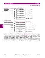
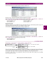
a) MAIN MENU
PATH: SETTINGS
CONTROL ELEMENTS
MONITORING ELEMENTS
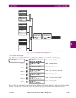
b) CT TROUBLE ZONE
PATH: SETTINGS
CONTROL ELEMENTS
MONITORING ELEMENTS
CT TROUBLE ZONE 1(4)
The CT Trouble feature is available only when
PRODUCT SETUP
B90 FUNCTION
B90 FUNCTION
is set to "Protection".
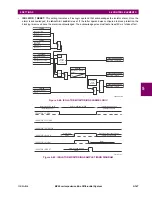
This element uses the differential current calculated in accordance with the bus configuration programmed under Bus Zone
1. Operation of this element is therefore completely dependent on the dynamic bus replica, which must be defined first. The
bus differential zones are defined using the path
SETTINGS
SYSTEM SETUP
BUS
. The CT Trouble element 1 detects
CT problems in any of the circuits actually connected to the differential zone defined as Bus Zone 1.
The
CT TROUBLE ZONE 1 PICKUP
setting specifies the differential current level that defines an abnormal bus state. If the dif-
ferential current in a given phase remains above this level for the time interval defined by the
CT TROUBLE ZONE 1 DELAY
setting, CT Trouble is declared for the given phase by setting the appropriate FlexLogic output operand. The operand may
be configured to raise an alarm and block the bus differential function for the corresponding zone of protection.
MONITORING
ELEMENTS
CT TROUBLE ZONE 1
MESSAGE
CT TROUBLE ZONE 2
MESSAGE
CT TROUBLE ZONE 3
MESSAGE
CT TROUBLE ZONE 4
MESSAGE
BUS REPLICA
CT TROUBLE ZONE 1
CT TROUBLE ZONE 1
FUNCTION: Disabled
Range: Disabled, Enabled
MESSAGE
CT TROUBLE ZONE 1
PICKUP: 0.100 pu
Range: 0.020 to 2.000 pu in steps of 0.001
MESSAGE
CT TROUBLE ZONE 1
DELAY: 1.0 s
Range: 1.0 to 60.0 s in steps of 0.1
MESSAGE
CT TROUBLE ZONE 1
TARGET: Self-reset
Range: Self-reset, Latched, Disabled
MESSAGE
CT TROUBLE ZONE 1
EVENTS: Disabled
Range: Disabled, Enabled
Содержание B90
Страница 10: ...x B90 Low Impedance Bus Differential System GE Multilin TABLE OF CONTENTS ...
Страница 50: ...2 20 B90 Low Impedance Bus Differential System GE Multilin 2 3 SPECIFICATIONS 2 PRODUCT DESCRIPTION 2 ...
Страница 118: ...4 28 B90 Low Impedance Bus Differential System GE Multilin 4 3 FACEPLATE INTERFACE 4 HUMAN INTERFACES 4 ...
Страница 284: ...5 166 B90 Low Impedance Bus Differential System GE Multilin 5 8 TESTING 5 SETTINGS 5 ...
Страница 334: ...10 8 B90 Low Impedance Bus Differential System GE Multilin 10 2 BATTERIES 10 MAINTENANCE 10 ...
Страница 338: ...A 4 B90 Low Impedance Bus Differential System GE Multilin A 1 PARAMETER LISTS APPENDIX A A ...
Страница 460: ...C 30 B90 Low Impedance Bus Differential System GE Multilin C 7 LOGICAL NODES APPENDIX C C ...
Страница 476: ...E 10 B90 Low Impedance Bus Differential System GE Multilin E 1 IEC 60870 5 104 APPENDIX E E ...
Страница 502: ...viii B90 Low Impedance Bus Differential System GE Multilin INDEX ...


