


GE Multilin
B90 Low Impedance Bus Differential System
5-85
5 SETTINGS
5.2 PRODUCT SETUP
5
EXAMPLE 3: PILOT-AIDED SCHEMES
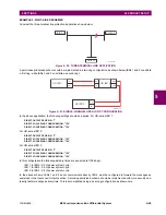
Consider the three-terminal line protection application shown below:
Figure 5–20: THREE-TERMINAL LINE APPLICATION
A permissive pilot-aided scheme could be implemented in a two-ring configuration as shown below (IEDs 1 and 2 constitute
a first ring, while IEDs 2 and 3 constitute a second ring):
Figure 5–21: SINGLE-CHANNEL OPEN LOOP CONFIGURATION
In the above application, the following settings should be applied. For UR-series IED 1:
DIRECT OUTPUT DEVICE ID:
“1”
DIRECT I/O CH1 RING CONFIGURATION:
“Yes”
DIRECT I/O CH2 RING CONFIGURATION:
“Yes”
For UR-series IED 2:
DIRECT OUTPUT DEVICE ID:
“2”
DIRECT I/O CH1 RING CONFIGURATION:
“Yes”
DIRECT I/O CH2 RING CONFIGURATION:
“Yes”
For UR-series IED 3:
DIRECT OUTPUT DEVICE ID:
“3”
DIRECT I/O CH1 RING CONFIGURATION:
“Yes”
DIRECT I/O CH2 RING CONFIGURATION:
“Yes”
In this configuration the following delivery times are expected (at 128 kbps):
IED 1 to IED 2: 0.2 of power system cycle;
IED 1 to IED 3: 0.5 of power system cycle;
IED 2 to IED 3: 0.2 of power system cycle.
In the above scheme, IEDs 1 and 3 do not communicate directly. IED 2 must be configured to forward the messages as
explained in the
Inputs and Outputs
section. A blocking pilot-aided scheme should be implemented with more security and,
ideally, faster message delivery time. This is accomplished using a dual-ring configuration as shown here.
842713A1.CDR
UR IED 1
UR IED 2
UR IED 3
842714A1.CDR
UR IED 1
TX1
RX1
UR IED 2
RX2
TX2
RX1
TX1
UR IED 3
RX1
TX1
Содержание B90
Страница 10: ...x B90 Low Impedance Bus Differential System GE Multilin TABLE OF CONTENTS ...
Страница 50: ...2 20 B90 Low Impedance Bus Differential System GE Multilin 2 3 SPECIFICATIONS 2 PRODUCT DESCRIPTION 2 ...
Страница 118: ...4 28 B90 Low Impedance Bus Differential System GE Multilin 4 3 FACEPLATE INTERFACE 4 HUMAN INTERFACES 4 ...
Страница 284: ...5 166 B90 Low Impedance Bus Differential System GE Multilin 5 8 TESTING 5 SETTINGS 5 ...
Страница 334: ...10 8 B90 Low Impedance Bus Differential System GE Multilin 10 2 BATTERIES 10 MAINTENANCE 10 ...
Страница 338: ...A 4 B90 Low Impedance Bus Differential System GE Multilin A 1 PARAMETER LISTS APPENDIX A A ...
Страница 460: ...C 30 B90 Low Impedance Bus Differential System GE Multilin C 7 LOGICAL NODES APPENDIX C C ...
Страница 476: ...E 10 B90 Low Impedance Bus Differential System GE Multilin E 1 IEC 60870 5 104 APPENDIX E E ...
Страница 502: ...viii B90 Low Impedance Bus Differential System GE Multilin INDEX ...


