


- 12 -
constantly unless escaped from the au tomatic test interface when the test is completed or
the test is interrupted manually through pressing down controller. After the completion of
the test, select “Print”
、
“Save”or “Print”.
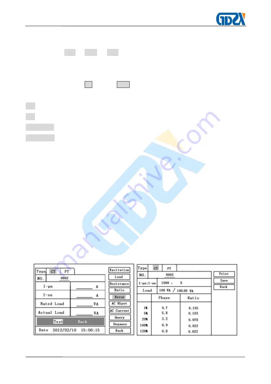
7. Error Test
1) CT Error Test (connection mode shown in Figure 4)
Move the controller to“CT”, Select Error to enter CT Error test interface (Figure 26).
Connect the CT primary side to P1 and P2, and the CT secondary side to S1 and S2,
I-pn
:
Setting range of primary output current: 0
~
1000A.
I-sn
:
1A or 5A.
Rated Load
:
The capacity of analyzer.
Actual Load
:
According to the rated load setting, automatic calculation of load and light load
of two kinds of state values (light load to full 25%).
After checking the correct wiring, Turn on the output. Move the controller to “Test” item to
start the test. With increasing of AC output to the primary side of CT, the current values
measured on the circuits on the primary and secondary sides will be displayed on the
screen in real time. After the test, the error test result will be worked out
automatically(Figure 27).
During the test process, the controller will be displayed on the “Test” item and flashes
constantly unless escaped from the automatic test interface when the test is completed or
the test is interrupted manually through pressing down controller. After the completion of
the test, select “Print”
、
“Save”or “Print”. If the display is 9, then the error exceeds the display
range, please check the setting value.
Figure 26
Figure 27
Содержание ZXHQ-A+ CT
Страница 1: ...ZXHQ A CT PT Characteristics Tester ...