


- 10 -
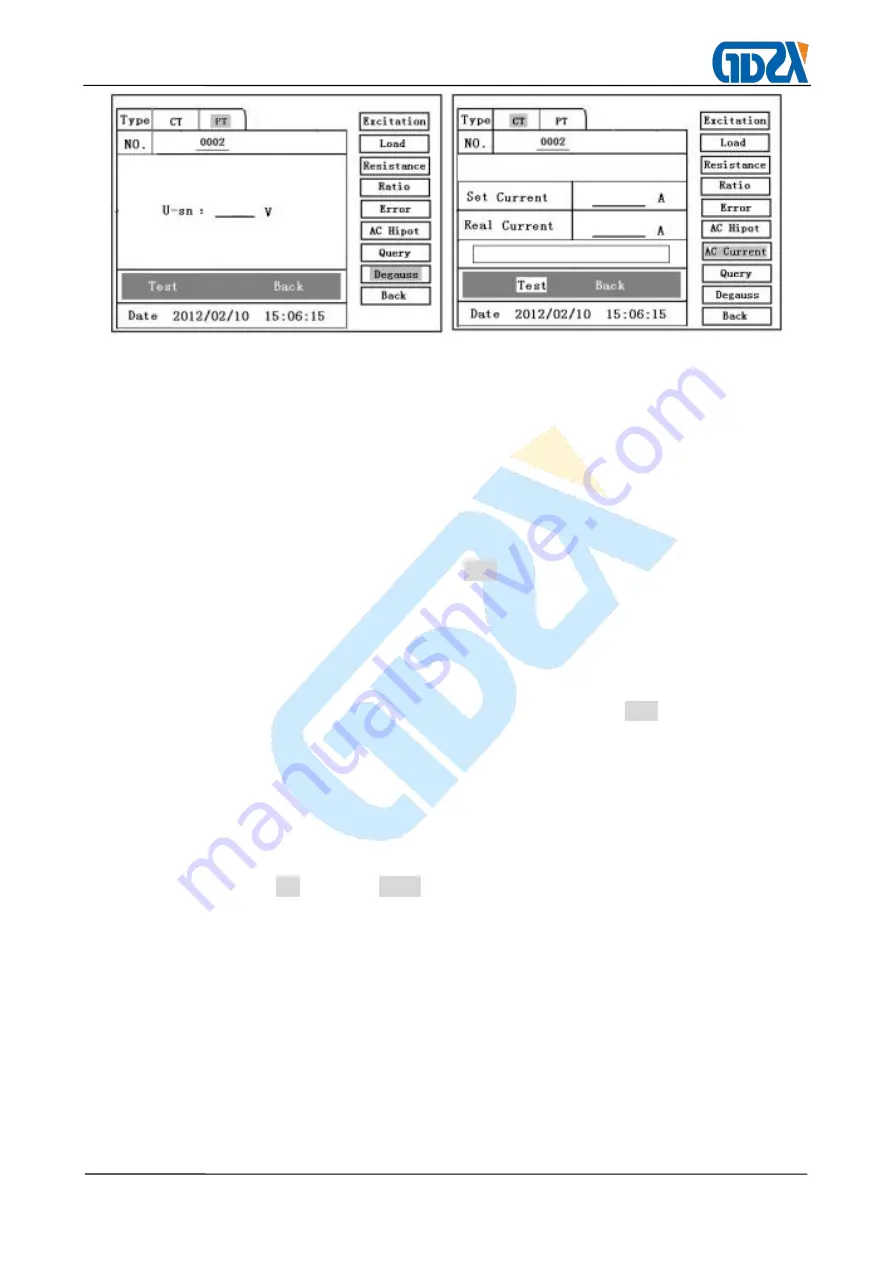
Figure 22
Figure 23
5.
AC Current:Current Output
(connection mode shown in Figure 5)
Set Currrent: 0
~
1000A,
Selection of output current (Figure 23): maximum output current from P1 and P2
terminals of the tester. With the changing of the operating voltage, the actual output current
will change with a deviation of 15%, which won’t affect the application. After the completion
of the setting, turn on the output, and select “Test” item. When the output current of the
equipment reaches the setting value, it will be held for a period of time (the holding time is
about 10MIN for the setting current less than 300A,between 300A and 500A the holding
time is about 2MIN, the holding time is about 3S for the setting current greater than 500A.)
During the test process, the controller will be displayed on the “Test” item and flashes
constantly unless automatically escaped when the test is completed or the test is
interrupted manually.
6. Ratio
:
Ratio and Polarity Test
1) CT Transformation Ratio and Polarity Test (connection mode shown in Figure 4)
Move the controller to“CT”, Select Ratio to enter CT transformation ratio test interface
(Figure 20). Connect the CT primary side to P1 and P2, and the CT secondary side to S1
and S2,
Parameter Setting: as shown in Figure 24,
I-p
:
Setting range of primary output current: 0
~
1000A.
I-s
:
1A or 5A.
After checking the correct wiring, Turn on the output. Move the controller to “Test” item to
start the test. With increasing of AC output to the primary side of CT, the current values
Содержание ZXHQ-A+ CT
Страница 1: ...ZXHQ A CT PT Characteristics Tester ...