13/52
EN
•
Place the sleeve (11) on the valve case and lock it with the circlip (12).
•
Test the function of the assembled gas outlets by connecting a male
quick coupling for the correct gas.
•
Reject enclosed details intended for recessed outlets.
Keep all equipment, also hands, tools, working clothes clean and free
from grease or oil.
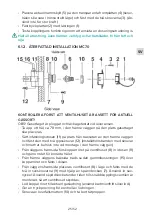
6.1.7. EXPOSED INSTALLATION MEDIUNIT
J
I
H1
E
L
H2
K
L
E
H
I
•
For axial housing (H2): drill a hole for axial inlet connection into the bot-
tom (marked) of the installation box (J) and into the wall. Seal the radial
hole with plug (K) to protect installation box (J).
•
For radial housing (H1): continue by the next point.
•
Place housing (H1 or H2) in the installation box (J) together with the lock-
ing plate (I) as shown on the picture and fix with three screws M5x12 (E).
•
Fix completed set with two screws (L). Holes for screws are marked in
the installation box (J).
•
For radial housing (H1): Push the plug (K) on the pipe to seal the radial
hole on the installation box (J).
•
Connect TU to the medical gas supply:
•
Connect radial housing (H1) by soldering the pipe to the pipeline ac-
cording to EN ISO 7396-2 standard.
•
Connect axial housing (H2) by connecting the hose to the axial con-
nection according to EN ISO 5359 standard.


