11/52
EN
If TU is being fixed in the wall by plastering, seal the four holes (O) need-
ed for fixation of the cover by insulating tape to protect them against
clogging during plastering.
•
Place housing (H1 or H2) in the installation box (J) together with the lock-
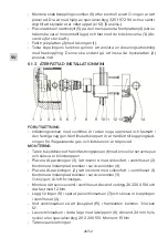
ing plate (I) as shown on the picture and fix with three screws M5x12 (E).
•
For radial housing (H1): Push the plug (K) on the pipe to seal the radial
hole on the installation box (J).
•
Connect TU to the medical gas supply:
•
Connect radial housing (H1) by soldering the pipe to the pipeline ac-
cording to EN ISO 7396-2 standard.
•
Connect axial housing (H2) by connecting the hose to the axial con-
nection according to EN ISO 5359 standard.
Keep all equipment, also hands, tools, working clothes clean and free
from grease or oil.
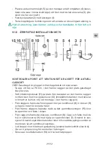
6.1.5. EXPOSED INSTALLATION MC70
FIRST CHECK THAT THE VALVE BODY IS FOR THE CORRECT TYPE OF
GAS!
The valve is plugged and leakage-tested upon delivery.
•
Mark out where to place the outlet valve.
•
Place the valve body (8) in position on the wall and fasten it with the two
enclosed plaster screws (12).
•
Solder the copper pipe to the correct gas pipe (use cadmium-free silver
solder.)
•
Make a pressure test of the pipe connection. Use the protecting cover
until the valve is mounted, so that dust will not contaminate the valve
body.
•
Unscrew the connecting nut (10) and remove the tightening plug.


