background image

22

  |  

User Guide  |  Heart and Lung Sounds  |  

Heart and Lung 
Sounds

Overview

The Heart and Lung Sounds teaching system is 

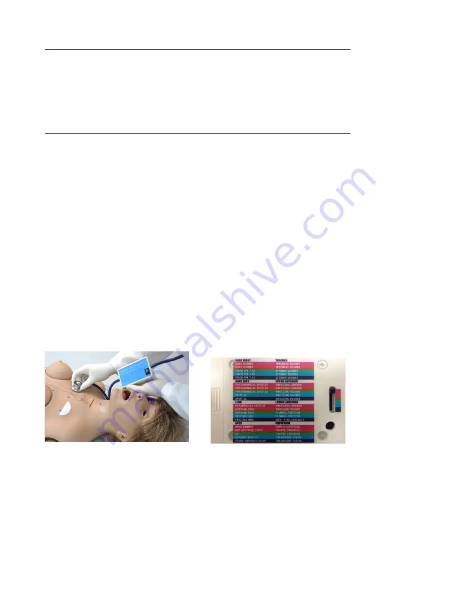
a tool used for auscultation training. The system 

is  composed  of  a  Virtual  Stethoscope™  and 

RFID  sensors  located  beneath  the  skin  of  the 

simulator. 

Incorporated  in  the  Virtual  Stethoscope  is  a 

control box with:

•  Power switch
•  Battery life status
•  Sounds menu

The  torso  of  the  simulator  has  numerous 

removable identiication dots located where each 

of the heart and lung sounds are normally heard. 

These colored dots can be removed at any time 

to palpate and ind the auscultation sites on the 

front  and  the  back  of  the  simulator.  The  torso 

of  the  simulator  also  features  ribs  and  lungs, 

useful for palpating each site. Each auscultation 

location relates to the physiology of the torso.

Setup

1.  The  Virtual  Stethoscope  is  powered  by  a 

conventional  9V  battery.  Open  the  battery 

cover  on  the  back  of  the  control  box  and 

install the battery. Close the cover.

2.  Locate  the  small  stereo  jack  on  the  control 

box and attach the speakers provided. Plug 

the speakers into a conventional 120V/60 Hz 

wall outlet and turn the speakers on.

The  speakers  provide  external  feedback  of 

the  auscultation  sounds.  If  the  speakers  are 

disconnected, only the student will hear the heart 

and lung sounds through the ear pieces on the 

virtual stethoscope.

Instructions for Use

1.  Locate the ON/OFF switch on the front of the 

control box and turn it on.

2.  Palpate  the  simulator  and  place  the  bell  of 

the virtual stethoscope at the 5th Intercostal 

Space on the left side of the simulator along 

the midclavicular line. This is the APEX point 

where sounds from the mitral valve and the 

left side of the heart are best heard. By placing 

the  “bell”  over  the  ID  disk  embedded  within 

the ifth intercostal space you will hear one of 

the ive possible sounds APEX heart sounds.

The  back  of  the  control  box  contains  a  label 

and a ive position slide switch. Each of the ive 

positions is color coded: red, orange, green, blue 

and black.

3.  Place the switch in the red position and hear 

the  sounds  highlighted  in  red  at  the  nine 

locations on the front and the four locations on 

the back of the simulator. Change the switch 

to  the  green  position  and  hear  a  different 

sound menu at the locations on the front and 

back of the simulator. Alternatively, you may 

want  to  choose  one  position  and  move  the 

slide switch through each of the ive sounds 

available. 

Содержание Super Chloe S222.100

Страница 1: ...oe Patient Care Simulator S222 100 Gaumard Simulators for Health Care Education Super Chloe is an interactive educational system developed to assist a certiied instructor It is not a substitute for a...

Страница 2: ...2 User Guide Super Chloe...

Страница 3: ...uper Chloe Overview 10 Airway 10 Nasal and Oral Intubation 10 Tracheostomy Care 11 Breathing 11 Pulmonary Ventilation 11 Circulation 12 Pulses 12 IV Arm 12 Systemic 14 Teeth and Tongue 14 Ears Nose an...

Страница 4: ...ns for Use 22 Menus 23 BP Arm Features Overview 25 Features 25 Palpable Pulse 25 Korotkoff Sounds 25 Auscultation 25 Omni Code Blue and BP Arm Using Omni Code Blue 26 Main Screen 26 Feedback Graphics...

Страница 5: ...not stack or store heavy materials on top of the carton Storage temperature 32 113 F 0 45 C Humidity 40 60 non condensing IV ARM Treat the simulator with the same precautions that would be used with a...

Страница 6: ...against soiled surfaces ink or newsprint The stoma material is absorbent MAINTENANCE Prevent items from resting or pressing against the stomas as indentations will form on the pressure points The stom...

Страница 7: ...assemble the internal components of the simulator unscrew one knob at the end of the rod 2 Pull from the side of the rod where the second knob is attached 3 Remove the rod from within the white guide...

Страница 8: ...this procedure LEG ASSEMBLY 1 Place the simulator on a lat surface 2 Remove the wing nuts washers and springs from the bolts on the hips 3 Remove the IM pad from each leg and slide the bolt through th...

Страница 9: ...unauthorized diagnostic equipment using the communication cable Ethernet cable Doing so will cause serious damage to the equipment POWER SUPPLY Connect the power supply to the power input located on...

Страница 10: ...urinary catheterization Medium skin tone is the standard simulator color light or dark skin is available at no extra cost Multiple heart sounds Multiple lung sounds NG OG and otic exercises Radial pu...

Страница 11: ...ded after each exercise SURGICAL TRACHEA REPAIR 1 Lift the chest skin of the simulator to reveal the chest cavity 2 Locate the trachea 3 Remove the tape enclosing the trachea 4 Use the provided tape t...

Страница 12: ...uscular injection site in the deltoid area Simulated cephalic basilic antecubital radial and ulnar veins Subcutaneous injection areas on the volar side of the forearm and the lateral side of the upper...

Страница 13: ...9 Close the adjustable clamp of the drainage tube 10 Perform intravenous subcutaneous and intramuscular procedures 11 To vary the blood pressure in the vasculature of the arm attach the tube with squ...

Страница 14: ...Shake vigorously until mixture is fully dissolved Systemic TEETH AND TONGUE The simulator is supplied with normal size teeth and tongue The upper and lower dentures are removable TEETH ASSEMBLY DISAS...

Страница 15: ...oid quadriceps and upper gluteal region All injection pads are easily removed and replaced BREAST PALPATION AND EXAMINATION The simulator is provided with two sets of interchangeable male and female b...

Страница 16: ...lostomy INTERNAL RESERVOIRS MAXIMUM CAPACITY Tank Capacity Stomach 750 ml Bladder Suprapubic Stoma 1800 ml Rectum Colostomy 1800 ml Ileostomy 650 ml Ear Canal 10 ml Hospital Care Capabilities WARNING...

Страница 17: ...he bladder reservoir SIMULATING BLADDER CONTRACTION Catheterization exercises may be carried with the aid of an auxiliary tank on a stand 1 Fill the auxiliary tank with luid and place on provided stan...

Страница 18: ...epsis and disinfection Use an 18 Fr catheter smaller catheters may cause leakage Lubricate the distal end of the catheter before insertion ASSEMBLY INSTRUCTIONS 1 Remove the red adaptor from the ureth...

Страница 19: ...e breast inserts Instructions for Use Breast examination should be done with the simulator in a semi upright position 1 Place the desired breast s in place and attach the soft vinyl brassiere onto the...

Страница 20: ...discreet nodes on one side a somewhat larger node on the other side and a very discreet puckered area around the nipple This breast represents various stages of ibrocystic disease which is due to an...

Страница 21: ...way subclavian pathway and internal mammary pathway are shown and are easily palpable Initially the instructor may ind it worthwhile to examine and palpate the various pathological breasts without the...

Страница 22: ...t and turn the speakers on The speakers provide external feedback of the auscultation sounds If the speakers are disconnected only the student will hear the heart and lung sounds through the ear piece...

Страница 23: ...rdynamic and has elevated cardiac output Mid Systolic Click Patient has mitral prolapse which produces a mid systolic click heard during inspiration S3 Sound Patient has a readily heard third heart so...

Страница 24: ...rn and position remain constant Similar to but lower in pitch than crackles Posterior Four Sites Medium Fine Crackles These noises begin about mid inspiration and progressively increase in intensity u...

Страница 25: ...l adjust automatically The sounds are silenced automatically if the auscultatory gap is enabled AUSCULTATION The simulator operates with a modiied blood pressure cuff Connect the BP cuff extension to...

Страница 26: ...s session CODE BLUE NAVIGATION MENUS Edit the simulator settings using the navigation menus Select a menu item by pressing the soft key buttons located on the right side of the controller Each menu ha...

Страница 27: ...ATION MENU Press CALIB to access additional menu selections CALIBRATING CHEST COMPRESSIONS The simulator is pre calibrated to current CPR guidelines at time of manufacture If the CPR guidelines change...

Страница 28: ...Omni will display DONE 7 Press SAVE RESETTING OMNI S PRESSURE SENSOR It is recommended that the Omni s pressure sensor is reset at altitudes greater than 1000 ft to avoid inaccurate compressions and...

Страница 29: ...evious screen The default value for the blood pressure is 120 80 mmHg PULSE MENU Use this menu to set the heart rate Adjust the beats per minute using the and buttons Press OK to save the changes and...

Страница 30: ...alibration settings CALIBRATION INSTRUCTIONS 1 Assemble the system and turn Omni on 2 Place the blood pressure cuff on the arm 3 Connect the cuff s extension to connector on the control panel 4 Select...

Страница 31: ...n Press OK to accept the changes SERIAL NUMBER View Omni and Simulator serial number Press OK to return to the HELP menu CPRLink CRPLink is an application that enables monitoring and logging of compre...

Страница 32: ...ni 3 Connect the USB cable to Omni and to the USB port of your PC Omni will display a heart icon on the lower left side of the screen when a connection with the PC has been established WARNING Do not...

Страница 33: ...Ventilation time elapsed since the last ventilation performed TRAINER The CPRLink application generates visual and audible cues of the compression to ventilation ratio programmed in the CPR Options me...

Страница 34: ...tcut icon located on the upper right side of the application The Provider Actions screen consists of four different areas from top to bottom session info team logging buttons provider action buttons a...

Страница 35: ...he vertical bars are teal colored While there is an active provider every time a Provider Action or Evaluation log entry is created it will have the name of the provider as follows 00 07 41 Steve Park...

Страница 36: ...esponsiveness SPECIAL BUTTON The special button adds additional functionality to the provider actions section The button allows the facilitator to be more speciic on the provider action he she wishes...

Страница 37: ...acilitator can quickly log actions from the Provider Actions section and make the entry more speciic using the Team Logging feature The following is an example of an Action entry 00 07 24 Action Asses...

Страница 38: ...simulation session Clear out log page Restart the session clock The session clock is located at the bottom of the Log box You can also start a new session by clicking on the session clock drop down me...

Страница 39: ...on at any time by going to File Exit or by clicking on the red x button at the top right corner of the CPRLink SET UP OPTIONS The Options window contains the parameters accessible to the user for coni...

Страница 40: ...hest compressions or artiicial ventilations The procedures for each speciic calibration are described in the sections below CHEST COMPRESSIONS ARTIFICIAL VENTILATIONS This tool allows you to calibrate...

Страница 41: ...successfully recorded The wizard prompts you with 2 2 Performasecondcorrectchestcompression A green illed oval indicates that the chest compression was successfully recorded 3 Continue the process At...

Страница 42: ...ion never gets established or is lost Data cable is not connected Ensure the Ethernet cable is plugged into Omni and the simulator Verify the power cable is connected to the simulator Omni is not dete...

Страница 43: ...ble Any subsequent purchasers or users of the product acquire the product as is and this limited warranty does not apply This limited warranty applies only to the products manufactured and produced by...

Страница 44: ...SA Ofice hours Monday Friday 8 30am 4 30pm EST GMT 5 4 Summer Time General Information Gaumard ZOE Michelle Mike PEDI Susie Simon Susie Simon Code Blue SIMA Models SIMA GYN AID Virtual Instruments Cod...

Отзывы: