49
A.
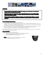
Rubber Gasket. B. Base Plate. C. Camera Ball.
D. Camera Collar. E. Retainer Ring
1.
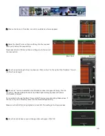
Disassemble the camera into its five major parts, A, B, C, D, E and carefully
place all parts in a clean work area.
2.
Position the Base Plate (B), in the mounting location. Ensure that there are no
gaps between the Base Plate (B) and the mounting surface. If there are gaps,
relocate the camera to a position where there are no gaps.
3.
Note the location where the camera harness will come though the bodywork of
the vehicle. Drill a ¾” hole in this location. This ¾” hole MUST be directly in the
center of the Base Plate (B) to allow for the terminal end of the camera
harness to correctly connect to the Camera Ball (C). When access behind the
camera is not possible, the cable can be routed from the side through one of
the cut out notches B1 in the camera base. The supplied grommets must be
used as part of this procedure.
4.
Center the camera over the ¾” hole and mark the location of the 4 screws
used to secure the camera base to the vehicle. Ensure that one of the camera
cut out notches, B1, is aimed at the viewing target. Use the supplied TEK, self-
tapping, screws to fix the camera base to the vehicle.
5.
Connect the Camera Ball Molex connector to the connector at the end of the
camera harness. Hold the Camera Ball firmly against the Base Plate with the
Microphone, C1, pointing downwards. Position Camera Collar (D) over Camera
Ball (C) with the lens window centered in the arched cut away in the Camera
Collar.
6.
Hold Camera Collar (D) securely while threading on the Retainer Ring (E) until
finger tight. Be careful not to cross-thread the components.
7.
To aim the Camera Ball (C), video from the camera can be viewed by connecting
a portable LCD/Monitor with an RCA connection to the front of the 816-HD, or,
by use of the ICD accessory available from Gatekeeper Systems.
8.
Re-position Camera Collar (D) prior to tightening down the Retainer Ring (E) so that it does not interfere with line of sight of
the camera and IR LED’s in the Camera Ball (C). Ensure the Camera Ball and Harness pigtail are not pinched or trapped
between the Camera Ball (C) or the Base Plate (B), it must be able to move freely.
9.
Tighten all accessible set screws on the Retainer Ring (E) and Camera Collar (D). In some installations several of the set
screws will not be accessible due to close proximity of the camera to the vehicles bodywork. In this situation tighten down
the set screws that are accessible.

