USE AND MAINTENANCE
52
-
cod. G19503220
ENGLISH
3.8 ROW MARKER DISK ADJUSTMENT
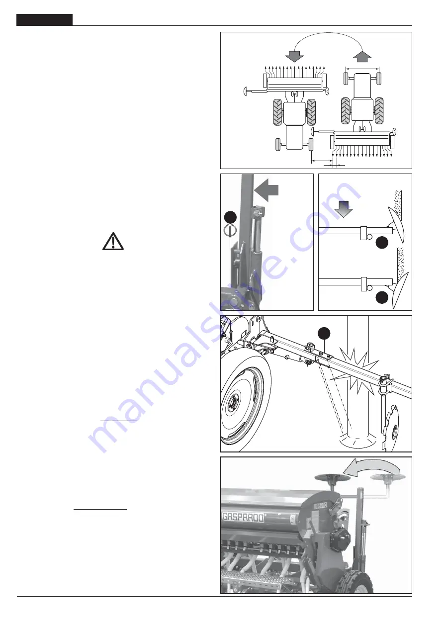
The row marker is an equipment that traces a reference line parallel
to the tracks of the tractor on the ground.
When the tractor fi nishes a passage and makes a U-turn, the front
wheel will begin the new row through alignment with the line traced
in parallel (Fig. 29). The row marker will continue to trace a parallel
reference line during its progress down each row. Marking at tractor
centre can be achieved with the row marker device correctly set.
The inversion of the row-marker arms is moved by means of a
control on the seeder.
3.8.1 HYDRAULIC ROW MARKER
The planting unit has a hydraulic row marker control device. The
hydraulic cilinders should be connected by their hydraulic pipes
to the hydraulic distributors of the tractor. Inside the hydraulic
cylinder boss there is a calibrated grub screw that could be clog-
ged by impurities in the oil. If there is malfunctioning, remove the
nipple and clean the hole of the calibrated grub screw, and then
put everything back paying attention to the direction of insertion
of the grub screw in the boss.
For correct functioning of the row marker arm, couple the
hydraulic tube for connection to the tractor to a dual acting
distributor.
When the system is not in use, protect the quick
coupling with its cap.
ATTENTION
Before starting up the row marking hydraulic circuit, using
your hand, apply slight pressure to the row marking arm in
the direction of the arrow (Fig. 30), then unhook the safety
devices on both arms (A, Fig. 30).
During road transport, block the safety devices on both row
marking arms (A, Fig. 30) in the vertical position, turn the row-
marker discs inwards towards the machine (Fig. 33). In this
confi guration, the hopper cover opening angle is reduced.
The row marker arms have a safety bolt (D, Fig. 32) so that the
planter unit structure will not be damaged. If they happen to bump
into an obstacle, this bolt will break and so the row marker arm will
rotate to leave the equipment structure intact.
3.8.2 ROW MARKING ARM LENGTH
See Fig. 29 and observe the following rules for correct row market
arm adjustment:
L = D (N +1) - C
2
where:
L= the distance between the outermost element and the row marker
D= the distance between the rows
N= the number of elements working
C= the tractor’s front wheelbase.
Example:
D=12,5 cm; N=24 elements; C=150 cm;
L=12,5 (24 + 1) -150 =81,25 cm
2
For normal soils the correct working position of the disc is that
shown in Fig. 31 ref. «B»; for strong soils turn it over as shown in
ref. «C» Fig. 31.
fi g. 30
fi g. 29
L
D
C
Avanzamento
Advancement
Avancement
fi g. 31
fi g. 33
A
B
C
fi g. 32
D
Содержание S MARIA 250
Страница 31: ...31 Notes cod G19503220 ...
Страница 59: ...59 Notes cod G19503220 ...
Страница 87: ...87 Notes cod G19503220 ...
Страница 115: ...115 Notes cod G19503220 ...
Страница 143: ...143 Notes cod G19503220 ...


