background image

GEBRAUCH UND WARTUNG

DEUTSCH

g

60

cod.  G19502491

3.0 BETRIEBS-ANLEITUNGEN

Um die besten Leistungen des Geräts zu erhalten, immer die
folgenden Anleitungen beachten.

ACHTUNG

Alle folgenden Wartungs-, Einstellun und
Vorbereitungsarbeiten dürfen  ausschließlich bei
ausgeschaltetem und gut blockiertem Schlepper,
herausgezogenem Schlüssel und auf dem Boden liegender
Sämaschine durchgeführt werden.

3.1 ÖLDYNAMISCHE ANLAGEN

ACHTUNG
Sicherheitsvorschriften für die Hydraulikanlage:
1) Beim Anschließen der Hydraulikschläuche an die

Hydraulikanlage des Schleppers ist darauf zu achten, dass
die Hydraulikanlagen der Ausrüstung und des Schleppers
nicht unter Druck stehen.

2) Bei funktionalen Verbindungen hydraulischer Art zwischen

Schlepper und Ausrüstung müssen Buchsen und Stecker
mit  verschiedenen Farben gekennzeichnet werden, damit
ein falscher Anschluss ausgeschlossen wird. Beim
Vertauschen von Anschlüssen besteht Unfallgefahr.

3) Die Hydraulikanlage steht unter hohem Druck. Aufgrund der

Unfallgefahr sind bei der Suche nach Leckagen geeignete
Geräte zu verwenden.

4) Beim Transport auf der Straße sind die

Hydraulikverbindungen zwischen Ausrüstung und Schlepper
zu trennen und an der speziellen Halterung zu befestigen.

5) Auf keinen Fall Pflanzenöl verwenden, da in diesem Fall eine

Beschädigung der Zylinderdichtungen nicht ausgeschlossen
werden kann.

6) Der Betriebsdruck der öldynamischen Anlage muss

zwischen 100 bar und 180 bar liegen.

7) Der vorgeschriebene Druck der öldynamischen Anlage darf

nie überschritten.

8) Den korrekten Anschluss der Schnellanschlüsse

überprüfen, da Beschädigungen an den Bauteilen der Anlage
auftreten könnten.

9) Das Austreten von unter hohem Druck stehendem Öl kann

zu Hautverletzungen mit der Gefahr schwerer Infektionen
führen. In diesem Fall ist sofort ein Arzt aufzusuchen. Aus
diesem Grund ist es strengstens verboten, öldynamische
Komponenten in der Schlepperkabine zu installieren. Alle
Komponenten der Anlage sind sorgfältig anzubringen, um
eine Beschädigung bei der Anwendung der Ausrüstung zu
vermeiden.

3.2 EINBAU AM SCHLEPPER

Die Sämaschine kann an jeden Schlepper mit universeller
Dreipunkt-Kupplung angekuppelt werden.

GEFAHR

Der Anbau am Schlepper ist sehr gefährlich. Bei der
Ausführung dieser Arbeit sehr vorsichtig sein und die
Anleitungen befolgen.

3.2.1 ANKUPPELN

Die korrekte Stellung Schlepper/Sämaschine wird bestimmt, indem
das Gerät auf eine waagrechte Ebene gestellt wird.
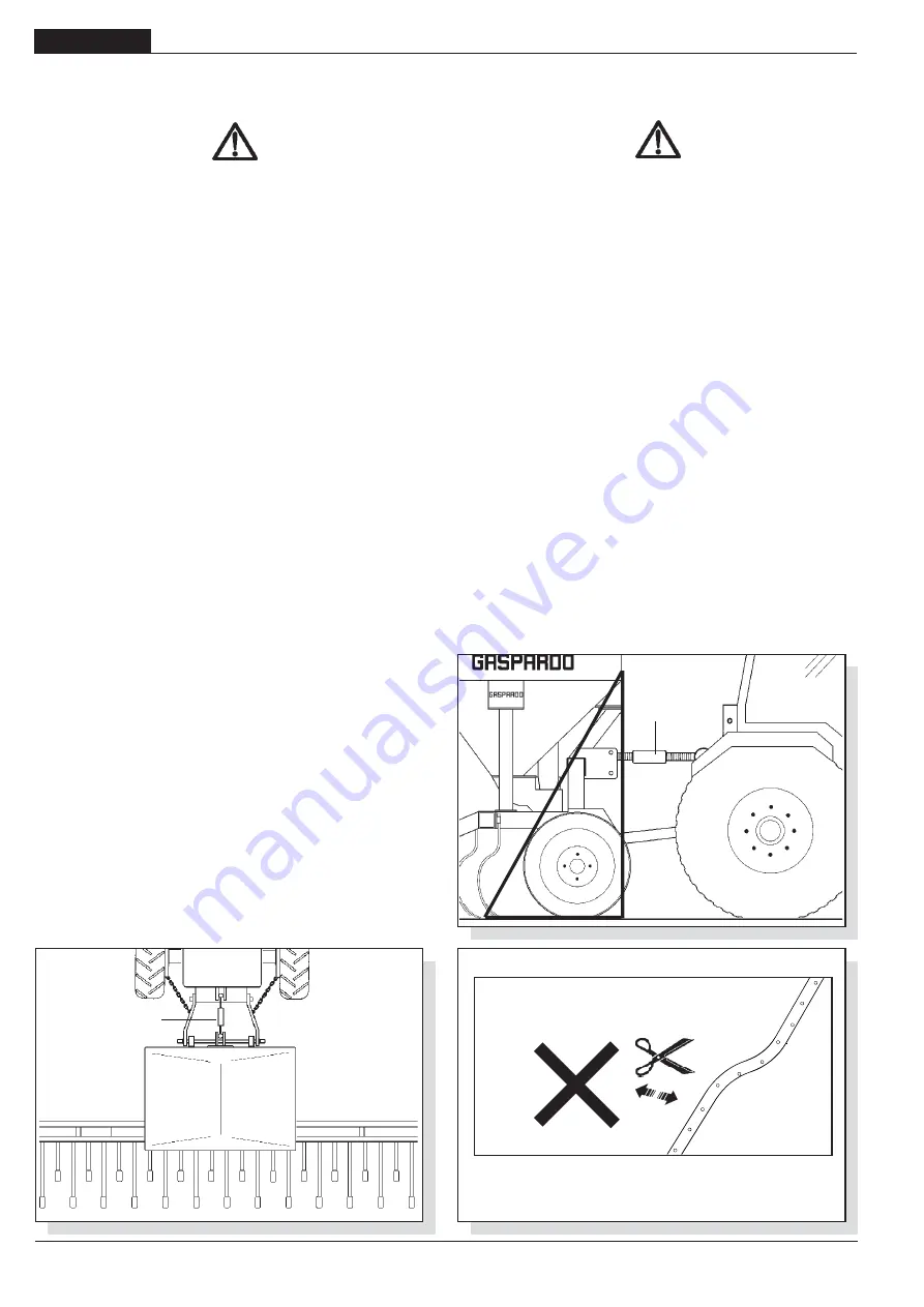
1)

Die Sämaschine an der Dreipunkte-Kupplung des Schleppers
ankuppeln; die Zapfen müssen mit ihren Stiften verbunden
werden; durch die Einstellstange (1 Abb. 8-9) die Sämaschine
in rechtwinklige Lage zum Boden (Fig.8) bringen.

2)

Die Bewegung der Parallelstangen des Schleppers auf der
horizontalen Ebene mittels der speziellen Stabilisatoren
blockieren, um die seitlichen Schwingungen der Ausrüstung
zu eliminieren. Es muss überprüft werden, dass sich die
Hebearme des Schleppers auf der gleichen Höhe vom Boden
befinden.

3)

Die Höhe der Schlepperhubarme einstellen:

  a) Den Hub der Hebearme des Schleppers in Arbeitsposition so

einstellen, dass eine ausreichende Spannweite nach unten
der Sämaschine garantiert werden kann. Ansonsten könnte
es bei Mulden im Saatbett zu unregelmäßigen Verteilungen
des Saatgutes aufgrund eines Schlupfs der Antriebsräder
der Sämaschine kommen (Verlust des Haftvermögens).

  b) In der Transportposition sind die Arme derart einzustellen,

daß die Sämaschine auf keinen Fall den Boden berühren kann.

4)

Die Gelenkwelle einkuppeln und sicherstellen, daß sie fest mit
der Zapfwelle verbunden ist. Sicherstellen, daß sich der Schutz
frei dreht  und ihn mit der vorgesehenen Kette befestigen.

fig. 10

cod. 19702401

fig. 8

fig. 9

1

1

Содержание PINTA

Страница 1: ...O E MANUTENZIONE USE AND MAINTENANCE GEBRAUCH UND WARTUNG EMPLOI ET ENTRETIEN EMPLEO Y MANTENIMIENTO Valido per Paesi UE ValidforEUmembercountries Valable dans les Pays UE Gilt f r EU Mitgliedsl nder...

Страница 2: ...ributoradjustmentandtest 38 3 5 Blowerdrive 41 3 5 1 Powertake offrpm 41 3 5 2 Oleo dynamicblowerdrive 41 3 6 Adjustingtheseedingdepth 44 3 7 Seedlevelinthehopper 44 3 8 Hoeadjustment 44 3 9 Loadingpl...

Страница 3: ...ation 98 6 0 Demantelement et elimination 98 Confotmitydeclaratione 125 1 0 Premisa 101 1 1 Garant a 101 1 1 1 Vencimientodelagarant a 101 1 2 Descripci ndelasembradora 101 1 3 Datostecnicos 102 1 4 I...

Страница 4: ...g 4 cod G19502491...

Страница 5: ...ffettuati dal cliente Qualora siano fatte modifiche senza l autorizzazione scritta del costruttore e qualora si siano utilizzati ricambi non originali 1 2 DESCRIZIONE DELLASEMINATRICE Questa attrezzat...

Страница 6: ...preavviso U M PINTA 400 PINTA 450 PINTA 500 PINTA 400 PINTA 450 PINTA 500 Versione Larghezza di trasporto m feet 4 00 13 4 50 14 9 5 00 16 5 4 00 13 4 50 14 9 5 00 16 5 Numero max file con stivaletti...

Страница 7: ...ig 2 con paranco o gr idonei e di sufficiente portata Questa operazione per la sua pericolosit necessario venga eseguita da personale preparato e responsabile La massa della macchina evidenziata nella...

Страница 8: ...fiante 3 Assolcatore a stivaletto 4 Assolcatore a disco semplice 5 Pedana 6 Dosatore fig 3 7 Punto di attacco inferiore 8 Azionamento idraulico marcafile 9 Piede di sostegno 10 Marcafile 11 Punto atta...

Страница 9: ...olo di caduta Non salire sulla macchina 6 Pericolo di intrappolamento State lontani dagli organi in movi mento 7 Pericolo di essere agganciati dall albero cardanico State lontani dagli organi in movim...

Страница 10: ...namento ed aver inserito sotto le ruote un ceppo o un sasso di bloccaggio di adeguate dimensioni 27 L applicazione di un attrezzatura supplementare al trattore com porta una diversa distribuzione dei...

Страница 11: ...nalazioni e protezioni adeguate 31 molto importante tenere presente che la tenuta di strada e la capacit di direzione e frenatura possono essere influenzati anche in modo notevole dalla presenza di un...

Страница 12: ...avi ferite ed infezioni In tal caso consultare immediatamente un medico Quindi si vieta asso lutamente di installare componenti oleodinamici nella cabina deltrattore Tuttiicomponentifacentipartedell i...

Страница 13: ...della circolazione stradale parte integrante dello stesso la stabilit del complesso trattore seminatrice pu variare causan do difficolt nella guida o nel lavoro impennamento o sbandamento del trattor...

Страница 14: ...acinesca e contemporaneamente la portata del rullo dosatore La posizione E1 Fig 16 consente un aper tura della saracinesca sulla scala graduata da 0 a 110 con la massima capacit di distribuzione del r...

Страница 15: ...one A Fig 17 ed al capo opposto del tubo posizionare un contenito re di raccolta Fig 18 Sganciare il cardano dalla trasmissione ruota e posizionarlo nell apposita sede come indicato in Figura 20 Inser...

Страница 16: ...278 263 279 171 291 271 294 281 293 182 312 290 312 295 311 195 331 306 330 313 328 208 354 323 348 332 347 219 374 340 366 349 365 231 395 357 384 365 383 241 415 374 94 26x12 00 12 Semente normale N...

Страница 17: ...onsumata sostituire la cinghia Mettere in trazione la cinghia serrando la vite C Fig 22 Serrare le viti prima allentate e rimontare il carter di protezione fig 22 B A C B 3 5 2AZIONAMENTOOLEODINAMICOD...

Страница 18: ...r inerzia anche dopo il disinserimento dell impianto o di un improvvisa avaria del siste ma Il circuito di ritorno dotabile anche di un radiatore a richie sta deve essere a bassa pressione max 10 bar...

Страница 19: ...25 Verificare il livello d olio nel moltiplicatore aggiungere se necessario ESSO SAE W80 90 Accendere il trattore ed azionare l impianto al minimo per qualche minuto portando la pressione costante al...

Страница 20: ...gli importante collocare il seme alla giusta profondit nel letto di semina La profondit di semina viene regolata singolarmente su ogni elemento agendo sulle molle a compressione A Fig 27 per mezzo del...

Страница 21: ...nell olio Se il funzionamento do vesse risultare irregolare smontare il nipplo e pulire il foro del grano calibrato quindi rimontare il tutto facendo attenzione al senso di inserimento del grano nell...

Страница 22: ...to alla macchina Montare i sei bracci supporto erpice 1 come indicato in figura Smontare i denti esterni 2 sulle tre sezioni dell erpice Accoppiare la barra quadra sui bracci supporto erpice 3 Rimonta...

Страница 23: ...bi discesa seme con macchina completamente sollevata per evitare la formazione di piegamenti quindi di rotture e la formazione di anse Fig 10 Verificare periodicamente durante il lavoro la perpendicol...

Страница 24: ...Durante la semina mantenere sempre il numero di giri della presa di potenza richiesta Controllare ogni tanto che gli elementi operatori non siano avvolti da residui vegetali o intasati di terra Contr...

Страница 25: ...e le avvertenze e le precauzio ni indicate sui contenitori Evitare il contatto con la pelle Dopo l utilizzo lavarsi accuratamente e a fondo Trattare gli olii usati in conformit con le leggi vigenti 5...

Страница 26: ...e C in dotazione come indicato in Figura 44 in sede di prova di rotazione non si tenuto conto detraendo lo del peso a vuoto del contenitore di raccolta Insufficiente escursione dei bracci del solleva...

Страница 27: ...g 27 cod G19502491 Notes...

Страница 28: ...g 28 cod G19502491...

Страница 29: ...t written authorization of the manufacturer and if non original spare parts have been used 1 2 DESCRIPTION OF THE SEEDER This farming implement can only be operated by a farming tractor equipped with...

Страница 30: ...right to change them without notice fig 1 1 2 3 5 7 4 6 U M PINTA 400 PINTA 450 PINTA 500 PINTA 400 PINTA 450 PINTA 500 Version Transport width m feet 4 00 13 4 50 14 9 5 00 16 5 4 00 13 4 50 14 9 5 0...

Страница 31: ...ig 2 with a suitable winch or crane of sufficient capacity Because of the danger involved this operation should be carried out by trained and responsible personnel The mass of the machine is on the id...

Страница 32: ...1 Seed hopper 2 Fan 3 Suffolk coulter 4 Single disc coulter 5 Footboard 6 Seed distributor 7 Lower coupling point 8 Row marker control lever 9 Supporting foot 10 Row marker 11 Upper coupling point 12...

Страница 33: ...tic protection 5 Danger of falling Do not get onto the machine 6 Danger of getting trapped Keep away from moving parts 7 Danger of getting hooked by the Cardanshaft Keep away from moving parts 8 Dange...

Страница 34: ...he protective devices are in perfect condition installed and in the safe position 13 It is absolutely prohibited to stand within the machine s radius of action where there are moving parts 14 It is ab...

Страница 35: ...haft 42 Use the chain provided to stop the Cardan shaft from rotating 43 Always check carefully that the Cardan shaft guard is always in position both during trans portation and operation 47 Frequentl...

Страница 36: ...the risk of serious wounds and infection Call a doctor immediately if such an incident occurs Therefore the installation of hydraulic components in the tractor driver s cab is strictly forbidden All...

Страница 37: ...becoming an integral part of it for the purposes of road travel the stability of the planting unit tractor complex may change and cause driving or operating difficulties rearing up or side slipping of...

Страница 38: ...ate to be modified which in turn modifies the capacity of the dosing roller at the same time The position E1 Fig 16 enables the gate to be opened on a graduated scale ranging from 0 to 110 with maximu...

Страница 39: ...at the other end of the tube Fig 18 Unhook the transmission wheel universal joint and position it in the seating for the purpose as indicated in figure 20 Insert the handle provided and block with the...

Страница 40: ...12 226 138 237 221 241 232 243 150 254 238 260 247 261 161 272 254 278 263 279 171 291 271 294 281 293 182 312 290 312 295 311 195 331 306 330 313 328 208 354 323 348 332 347 219 374 340 366 349 365 2...

Страница 41: ...g 22 If worn replace the belt Tension the belt by tightening the screws C Fig 22 Tighten the bolts loosened before and close the casing 3 5 2 OLEO DYNAMIC BLOWER DRIVE Safety The equipment is suitable...

Страница 42: ...s been disengaged or when there has been a sudden failure of the system The return circuit which can have a radiator incorporated on request must be low pressure max 10 bar otherwise the oil seal of t...

Страница 43: ...TENTION When it is not intended to distribute product but rather to use only the equipment to which it is applied disconnect the pump and the multiplier from the rear power take off and replace it in...

Страница 44: ...The planting depth is adjusted individually for each element by using the nut B to regulate the compression springs A Fig 27 Depending on the type of the type of soil either increase or decrease the c...

Страница 45: ...f there is malfunctioning remove the nipple and clean the hole of the calibrated grub screw and then put everything back paying attention to the direction of insertion of the grub screw in the boss Fo...

Страница 46: ...e Assemble the six harrow support arms 1 as shown in the figure Disassemble the outer teeth 2 on the three sections of the harrow Couple the square section bar to the harrow support arms 3 Reassemble...

Страница 47: ...tely hoisted to avoid bendings and consequently breaking of the tube as well as the formation of loops Fig 10 During the work regularly check that the equipment is perpendicular UNHOOKING DANGER Unhoo...

Страница 48: ...tion During the seeding operation always maintain the number of rotations for the requested power take off Check at times that the operating parts are not covered with vegetable residual matter or clo...

Страница 49: ...in contact After use wash the equipment thoroughly Treat the used oils and polluting liquids in conformity with the laws in force 5 0 1 WHEN THE MACHINE lS NEW After the first hours of work check that...

Страница 50: ...in equipment like indicated in Figure 44 during the rotation test the empty weight of the collecting container was not taken into account and deducted Insufficient movement of the hoist arms the plan...

Страница 51: ...g 51 cod G19502491 Notes...

Страница 52: ...g 52 cod G19502491...

Страница 53: ...ung des Herstelles Ver nderungen durchgef hrt werden oder keine Originalersatzteile verwendet werden 1 2 BESCHREIBUNG DER S MASCHINE Dieses landwirtschaftliche Ger t kann nur dann arbeiten wenn es zus...

Страница 54: ...gaben ohne Vorank ndigung zu ndern U M PINTA 400 PINTA 450 PINTA 500 PINTA 400 PINTA 450 PINTA 500 Version Transportbreite m feet 4 00 13 4 50 14 9 5 00 16 5 4 00 13 4 50 14 9 5 00 16 5 Max Reihenanza...

Страница 55: ...gneten Aufzug oder Kran mit ausreichender Tragkraft gehoben werden Diese gef hrliche Arbeit muss absolut durch geschultes und haftendes Personal ausgef hrt werden Das Maschinengewicht kann dem Identif...

Страница 56: ...1 Saatkasten 2 Gebl se 3 Suscharen 4 Einzelscheibenschar 5 Arbeitsb hne 6 Dosierger t 7 Dreipunktanschlu Unterlenker 8 Stellhebel f r Spurrei er 9 St tzfu 10 Spurrei er 11 Dreipunktanschlu Oberlenker...

Страница 57: ...ufenden Teilen Abstand halten 7 Gefahr von der laufenden Gelenkwelle erfasst zu werden Von laufenden Teilen Abstand halten 8 Gefahr f r Abtrennen der H nde N hern Sie sich nicht den laufenden Teilen 9...

Страница 58: ...eit mit der Maschine erst beginnen wenn alle Schutzvorrichtungen vollst ndig angebracht und in Sicherheitsposition sind 13 Es ist strengstens verboten sich in Bereichen aufzuhalten die in der N he sic...

Страница 59: ...Montage und die Sicherheit der Kardanwelle achten 42 Die Drehung des Kardanwellenschutzes mittels der mitgelieferten Kette verhindern 43 Stets auf den Kardanwellenschutz achten sowohl in Transport al...

Страница 60: ...schwerer Infektionen f hren In diesem Fall ist sofort ein Arzt aufzusuchen Aus diesem Grund ist es strengstens verboten ldynamische Komponenten in der Schlepperkabine zu installieren Alle Komponenten...

Страница 61: ...peln 3 3 STABILIT T VON S MASCHINE SCHLEPPER BEIM TRANSPORT Wenn eine S maschine an den Schlepper angekuppelt wird und somit gem Stra enverkehrsordnung zu einem Teil des Schleppers wird kann die Stabi...

Страница 62: ...ungsbereich des Schiebers und gleichzeitig den Durchsatz der Dosierrolle zu ver ndern Die Stellung E1 Abb 16 erm glicht das ffnen des Schiebers auf der Gradskala von 0 bis 110 und mit maximaler S leis...

Страница 63: ...welle vom Radgetriebe l sen und sie in den f r sie vorgesehenen Sitz wie in Abb 20 dargestellt positionieren Die beiliegende Kurbel einf gen und sie mit dem Schnappstift blockieren Die Kurbel in Fahrt...

Страница 64: ...13 128 218 205 223 212 226 138 237 221 241 232 243 150 254 238 260 247 261 161 272 254 278 263 279 171 291 271 294 281 293 182 312 290 312 295 311 195 331 306 330 313 328 208 354 323 348 332 347 219 3...

Страница 65: ...lockern A Abb 22 Die Mutter lockern B Abb 22 Einen verschlissenen Riemen sofort auswechseln Den Riemen spannen indem die Schraube festgezogen wird C Abb 22 Alle zuvor gelockerten Schrauben wieder fes...

Страница 66: ...l tzlichen Ausfall der lversorgung aufgrund seiner Massentr gheit nachlaufen kann Der lr cklauf in den auf Anfrage ein lk hler eingesetzt werden kann mu mit Niederdruck max 10 bar erfolgen andernfalls...

Страница 67: ...esehene Drehzahl Tabelle 5 bringen ACHTUNG Falls das Bodenbearbeitungsger t alleine und ohne S maschine betrieben werden soll die lpumpe und das Verteilergetriebe von der Zapfwelle abziehen und in die...

Страница 68: ...es t wird Die S tiefe wird auf jedem Element einzeln eingestellt indem mit Hilfe der Mutter B die Druckfedern A Abb 27 reguliert werden Je nach Beschaffenheit des Bodens kann der Druck der Feder erh h...

Страница 69: ...en der durch eventuell in l enthaltene Verunreinigungen verstopft werden kann Falls der Betrieb unregelm ig sein sollte ist der Nippel auszubauen und die ffnung des geeichten Stiftes zu reinigen Dann...

Страница 70: ...iert werden Abb 37 Die sechs Eggenhalterungsarme 1 montieren wie auf Abbildung gezeigt Au enz hne 2 auf den drei Feldern der Egge abmontieren Vierkantschiene auf den Eggenhalterungsarmen 3 befestigen...

Страница 71: ...hen der Schl uche f hren k nnen Eventuell ist die L nge der Schl uche gem Abbildung 10 den Arbeitsbedingungen anzupassen W hrend der Arbeit regelm ig kontrollieren dass die Ausr stung in der senkrecht...

Страница 72: ...rsten Stellung belassen Beim Auss en ist die Drehzahl des Nebenantriebs immer konstant zu halten Ab und zu kontrollieren da sich keine Pflanzen um die S emaschinenorgane gewickelt haben und da diese n...

Страница 73: ...snahmen immer aufmerksam lesen Kontakt mit der Haut vermeiden Nach Gebrauch die H nde sorgf ltig und gr ndlich waschen Alt l und umweltverschmutzende Fl ssigkeiten laut den geltenden Umweltschutzgeset...

Страница 74: ...n B und C als Leihgabe wie angegeben davon stellt 44 dar Bei der Rotationsprobe wurde das Leergewicht des Sammelbeh lters nicht ber cksichtigt und abgezogen Unzureichende Spannweite der Hubwerkarme di...

Страница 75: ...g 75 cod G19502491 Notes Notes Notes Notes Notes...

Страница 76: ...g 76 cod G19502491...

Страница 77: ...sans l autorisation crite du constructeur et en cas d utilisation de pi ces d tach es qui ne sont pas d origine 1 2 DESCRIPTION DE LA MACHINE Cet quipement agricole peut traveiller uniquement au moye...

Страница 78: ...0 PINTA 450 PINTA 500 PINTA 400 PINTA 450 PINTA 500 Version Largeur de transport m feet 4 00 13 4 50 14 9 5 00 16 5 4 00 13 4 50 14 9 5 00 16 5 N max de rangs avec soc nr Ecartement min avec soc cm in...

Страница 79: ...un palan ou une grue appropri s ayant une capacit suffisante Cette op ration qui est dangereuse sera effectu e par un personnel expert et responsable La masse de la machine appara t dans la plaque d i...

Страница 80: ...3 1 Tr mie 2 Soufflerie 3 Soc 4 Disque simple 5 Plate forme 6 Doseur 7 Point d attelage inf rior 8 Levier de commande traceur 9 Pied de souten 10 Traceur 11 Point d attelage superieur 12 Fiche de secu...

Страница 81: ...anes en mouvement vous risquez d y tre pris 7 Vous risquez d tre pris par l arbre cardans Ne pas s approcher des organes en mouvement 8 Danger de cisaillement des mains Ne vous approchez pas des parit...

Страница 82: ...rotection sont dans des conditions parfaites install s et en position de s curit 13 Il est absolument interdit de rester dans la zone de travail de la machine et notamment pr s des organes de mouvemen...

Страница 83: ...cardans 42 Bloquer la rotation de la protection de l arbre cardans par la cha ne pr vue cet effet 43 Contr ler soigneusement la protection de l arbre cardans en position de transport et de travail 44...

Страница 84: ...a nant de graves infections Dans ce cas consulterimm diatementunm decin Ilestdoncabsolument interdit d installer des composants ol odynamiques dans la cabine du tracteur Tous les composants faisant pa...

Страница 85: ...TRACTEUR Lorsqu un semoir est attel un tracteur devenant pour la circulation routi re partie int grante de ce dernier la stabilit de l ensemble tracteur semoir peut varier entra nant des difficult s...

Страница 86: ...f E Fig 13 16 permet de modifier l ou verture de la vanne et en m me temps le d bit du rouleau doseur La position E1 Fig 16 permet l ouverture de la vanne sur l chelle gradu e de 0 110 avec le maximum...

Страница 87: ...re extr mit du tube placer un bac de r colte Fig 18 D crocher le cardan de la transmission de la roue et le positionner dans le logement appropri comme indiqu en Fi gure 20 Ins rer la manivelle fourni...

Страница 88: ...199 186 22 8 11 4 27 5 13 75 29 3 14 65 203 195 213 128 218 205 223 212 226 138 237 221 241 232 243 150 254 238 260 247 261 161 272 254 278 263 279 171 291 271 294 281 293 182 312 290 312 295 311 195...

Страница 89: ...esserrer l crou B Fig 22 Si la courroie est us e la remplacer Tendre la courroie en serrant les vis C Fig 22 Resserrer toutes les vis et remonter le carter fig 22 B A C B 3 5 2INSTALLATIOND ACTIONNEME...

Страница 90: ...vation ou une panne impr vue du syst me Le circuit de retour qui peut tre galement quip d un radiateur sur demande doit tre basse pression max 10 bars en cas contraire la bague d tanch it du moteur ol...

Страница 91: ...pondant la condition de travail Tableau 5 ATTENTION S il ne faut pas distribuer du produit mais utiliser uniquement l outil appliqu d tacher la pompe et le multiplicateur de la prise de force arri re...

Страница 92: ...ffisamment du terrain il est important de placer la semence la juste profondeur dans le lit d ensemencement La profondeur de semis est r gl e individuellement sur chaque l ment en agissant sur les res...

Страница 93: ...accouplement du cylindre ol odynamique Si le fonctionnement n est pas r gulier d monter le raccord et nettoyer le trou du grain calibr Puis remonter le tout en veillant au sens d introduction du grain...

Страница 94: ...les six bras de support de la herse 1 d apr s la figure D monter les dents externes 2 sur les trois sections de la herse Accoupler la barre carr e sur les bras de support de la herse 3 Remonter les d...

Страница 95: ...ion de courbes et de pliages et par cons quent de ruptures Au besoin adapter les tuyaux en modifiant leur longueur selon Fig 10 V rifier p riodiquement au cours du travail la perpendicularit de l quip...

Страница 96: ...ement maintenir toujours le nombre de tours requis pour la prise de force Contr ler de temps en temps que les l ments ne soient pas envelopp s de r sidus v g taux ou colmat s par de la terre Contr ler...

Страница 97: ...ur les r servoirs Eviter tout contact avec la peau Apr s l utilisation se laver soigneusement les mains Traiter les huiles us es et les liquides polluants selon les lois en vigueur 5 0 1 QUAND LA MACH...

Страница 98: ...Fig 44 avec les cloisons B et C en dotation comme indiqu en Figure 44 lors de l essai de rotation on n a pas tenu compte du poids vide du r cipient de recueil en le retirant Course insuffisante des br...

Страница 99: ...g 99 cod G19502491 Notes...

Страница 100: ...g 100 cod G19502491...

Страница 101: ...abricante y si se hubiesen utilizado repuestos no originales 1 2 DESCRIPCI N DE LA SEMBRADORA Este apero agr cola puede operar s lo mediante un tractor agr cola con grupo elevador con enganche univers...

Страница 102: ...on reja nr Distancia min entre las lineas con reja cm inch 12 5 5 Numero mex de lineas con disco simple nr Distancia min entre las lineas con disco simple cm inch Capacidad del deposito de la semilla...

Страница 103: ...al efecto me diante aparejo o gr a id neos con suficiente capacidad Esta operaci n debido a su peligrosidad deber ser realizada por personal capacitado y responsable El peso de la m quina est indicado...

Страница 104: ...ador 3 Surcador a reja 4 Surcador a simple disco 5 Plataforma 6 Dosificador 7 Punto de enganche inferior 8 Palanca mando marcadora de hileras 9 Pie de apoyo 10 Marcadora de hileras 11 Punto de enganch...

Страница 105: ...a 6 Peligro de captura permanecer lejos de los rganos en movimiento 7 Peligro de quedar enganchados con el rbol card n Permanencer lejos de los rganos en movimiento 8 Peligro de corte para las manos N...

Страница 106: ...ositivos de protecci n est n intactos instalados y en posici n de seguridad 13 Es absolutamente prohibido aparcarse en el rea de acci n de la m quina en donde se encuentren partes en movimiento 14 Es...

Страница 107: ...a seguridad del rbol card n sea efectuado correctamente 42 Bloquear la rotaci n de la protecci n del rbol card n con la cadenilla en dotaci n 43 Tener mucho cuidado con la protecci n del rbol card n t...

Страница 108: ...En dicho caso consulte inmediatamente a un m dico Est terminantemente prohibido instalar componentes hidr ulicos en la cabina del tractor Todos los componentes que forman parte de la instalaci n se de...

Страница 109: ...E EL TRANSPORTE DE LA SEMBRADORA TRACTOR Cuando una sembradora se acopla a un tractor convirti ndose as en parte integrante del mismo para la circulaci n por la v a p blica la estabilidad del grupo tr...

Страница 110: ...mite modificar el campo de abertura de la persiana y simult neamente la capacidad del rodillo dosificador La posici n E1 Fig 16 permite una abertura de la persiana sobre la escala graduada de 0 a 110...

Страница 111: ...strado con la m quina A Fig 17 y en el extremo opuesto del tubo coloque un recipiente de recogida Fig 18 Desenganche el card n de la transmisi n de la rueda y col quelo en su alojamiento tal como mues...

Страница 112: ...3 195 213 128 218 205 223 212 226 138 237 221 241 232 243 150 254 238 260 247 261 161 272 254 278 263 279 171 291 271 294 281 293 182 312 290 312 295 311 195 331 306 330 313 328 208 354 323 348 332 34...

Страница 113: ...tueca B Fig 22 Si desgastada substituir la correa Colocar en tracci n la correa engrapando el tornillo C Fig 22 Engrapar todos los tornillos antes de aflojar y volver a montar el chasis de protecci n...

Страница 114: ...onectar la instalaci n o de una improvisa aver a en el sistema El circuito de retorno equipado tambi n con un radiador a pedido debe ser de baja presi n m x 10 bar porque en caso contrario se rompe el...

Страница 115: ...onstante en todo el circuito para evitar la inestabilidad del soplador Haga que el soplador llegue al n mero de revoluciones que corresponde a la condici n de trabajo Tabla 5 ATENCI N Cuando no tenga...

Страница 116: ...os g rmenes broten es importante que la semilla venga colocada a la correcta profundidad en la cama de la siembra La profundidad de la siembra se regula individual mente en cada elemento por medio de...

Страница 117: ...s en el aceite Si el funcionamiento fuera irregular desmonte la entrerrosca y limpie el orificio del pasador calibrado luego reinstale todo observando el sentido de introducci n del pasador en el cubo...

Страница 118: ...onte los seis brazos de soporte de la grada 1 como indicado en la figura Desmonte los dientes externos 2 en las tres secciones de la grada Acople la barra cuadrada sobre los brazos de soporte de la gr...

Страница 119: ...ormaci n de pliegues o dobleces causa de rupturas Eventualmente adaptarlos va riando la longitud as como mostrado en la Figura 10 Peri dicamente durante el trabajo controle que el equipo est perpendic...

Страница 120: ...tener el elevador hidr ulico en la posici n m s baja Durante el sembrado mantener siempre la cantidad de revoluciones de la toma de fuerza solicitadas Controlar de vez en cuando que los elementos oper...

Страница 121: ...ores Evitar el contacto con la piel Tras su utilizaci n lavarse de manera esmerada y a fondo Tratar los aceites utilizados y los l quidos contaminadores de conformidad con las le yes vigentes 5 0 1 CU...

Страница 122: ...en los cuales se sali afuera de semillas del sistema de dosificaci n Solamente en este caso substituir la protecci n A Fig 44 con las divisiones B y C en dotaci n como se indica figura 44 durante la...

Страница 123: ...g 123 cod G19502491 Notes...

Страница 124: ...g 124 cod G19502491...

Страница 125: ...idsvoorschriften vol gens de Europese Richtlijn 98 37 EG Voor de aanpassing van de machine werd de volgende geharmoniseerde norm gebruikt UNI EN ISO 4254 1 2006 EN 14018 2006 alsmede de technische spe...

Страница 126: ...RDO SpA Sede legale e stabilimento produttivo Via Marcello 73 35011 Campodarsego Padova Italy Tel 39 049 9289810 Fax 390499289900 Email info maschio com www maschionet com MASCHIO GASPARDOUSAInc 120 N...

Отзывы: