20
First the Local Service telephone number is displayed
followed by the customer identity display. After 10
seconds the serial number will automatically be
displayed on the next screen (for approximately 4
seconds).
The Continue
button can be used to advance to the
next screen. Use the Back
button to return to the
previous screen. The display will return to the normal
operating display when finished.
3.5 Using the menu system
To enter the menu system press the Continue
button. The menu system can be accessed during
normal channel monitoring, alarm or fault condition.
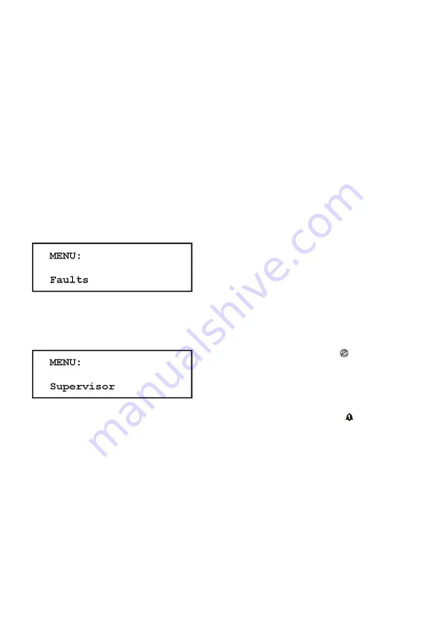
The message area will display the following screen:
Note: if the menu system has been accessed previously,
the menu item displayed will be the last actioned menu
item. For example, if you were using Supervisor mode
the last time, the menu display will show this:
Use the Up
and Down
buttons to scroll through the
menu list. To exit the menu press and hold the Accept/
Reset button or press Back
button as many times as
necessary.
Menu display
The top line of the message area displays the current
menu level. Some menu levels have submenus and
wizards that guide you through configuration. The lower
line displays the menu item, value or setting.
Use the Up
and Down
buttons to scroll through the
menu list, press Continue
to select the menu item.
Refer to figure 3.4 on page 24 for an overview of the
menu system.
Menu wizards
Wizards are an extension of the menu system to
guide the user through a process such as calibration.
A wizard menu will consist of selections, user prompts
and display status conditions during the process.
The Back
button can be used to return to the previous
screen or abort the wizard. The Down
and Up
buttons are used to alter a selection.
The Continue
button accepts the current selection
and continues to the next step of the wizard.
Wizards are available for Zero and Calibration menus in
Supervisor menu.
3.6 Inhibiting channels
Inputs can be temporarily inhibited so as not to cause
alarms. This may be necessary when calibrating
detectors, or when operations are carried out close
to a sensor which may trigger an alarm (for example,
soldering near a smoke detector). Input channels can be
inhibited individually or all at once. The ‘inhibit’ option is
available in the Supervisor Menu, see the Menu System
Overview on page 23 for details on how to access this
function.
When inhibited Gasmaster will:
■
Display the ‘inhibit’ symbol
on the channel
display for each affected channel.
■
Illuminate the yellow ‘Warning’ LED.
In the event of an alarm on an inhibited channel,
Gasmaster will:
■
Illuminate the Alarm symbol on the channel
display for the affected channel.
■
Illuminate the red alarm LED bar.
■
Display the alarm text message for the affected
channel.
Gasmaster will not:
■
Operate any relays associated with the affected
channel.
■
Drive external audible visual alarms.
■
Activate the internal sounder.
If it is necessary to permanently disable a channel, enter
Supervisor Mode and set the relevant detector Type
to Unused (see section 3.10 on page 23). The channel
display will then blank, and the power supply will be
removed from the detector.
3. Operation
Содержание Gasmaster
Страница 1: ...1 to 4 channel gas detection control panel Gasmaster Installation Operation and Maintenance Manual ...
Страница 12: ...9 2 Installation ...
Страница 28: ...25 Menu system overview ...


