Garudan GF-3131-447 MH Скачать руководство пользователя страница 17

© ANITA  


MP03100EN_180912  


17 


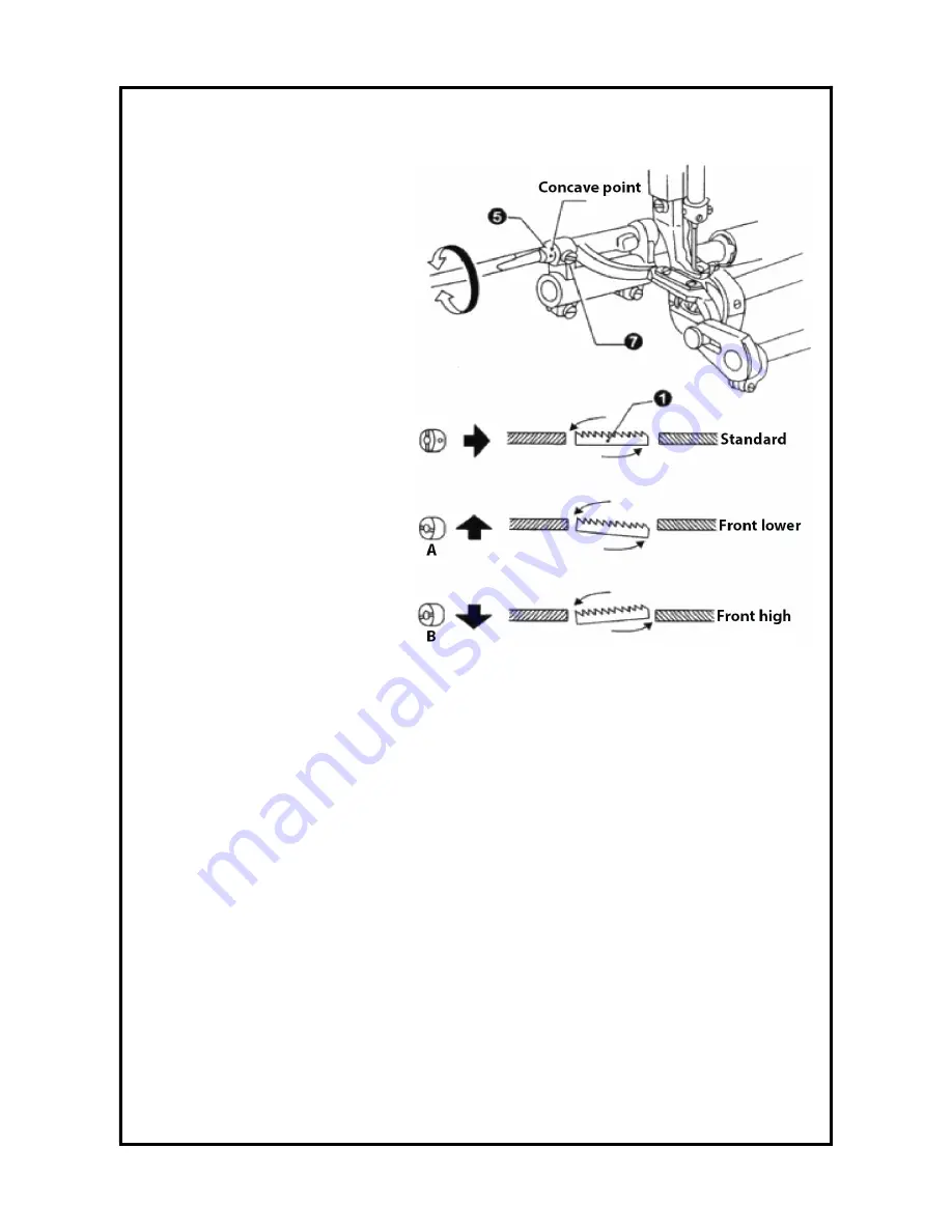
25. ADJUST THE HIGH OF THE FEED DOG 


Feed dog standard angle is: when the 

feed dog higher than needle plate and 

in the highest position. Braces 

concave point (5) on the crank 

eccentric shaft tags in a horizontal 

position. 

See Fig. (22).  


Turn the wheel make the feed dog 

to needle plate and in the 

highest position Loosen. 


Loosen the braces crank shaft 

screw (7). 


According to the standard of the 

feed dog angle position. 


Make the concave point mark 90° 

rotation adjustment. 


*


Feed dog in front of the lower. can 

prevent the fabric wrinkling (picture 

A). 


* Feed dog in front of the drive up, can prevent the cloth running deviation (picture B). 


Tighten braces crank shaft screw (7). 


After the feed dog angle adjustment, to adjust the Hight of the dog is necessary. 


Figure 22 

www.garudan.cz

Содержание GF-3131-447 MH

Страница 1: ...User manual GF 3131 447 MH ANITA B s r o Pr myslov 2453 7 680 01 Boskovice Czech Republic tel 420 516 454 774 420 516 453 496 fax 420 516 452 751 e mail info anita cz MP03100EN_180912...

Страница 2: ...rty of Anita B s r o and protected by copyright The use of this content without written consent of Anita B s r o is prohibited Copyright Anita B s r o 2018 VERSION CREATED ON APPROVED BY MP03100EN_180...

Страница 3: ...e stitch length 13 17 Stitching and reverse stitching 13 18 Adjust the thread tension 14 19 Adjust the pressure of presser foot 14 20 Adjust the length of the thread after trimming 15 21 Adjust thread...

Страница 4: ...r could suffer fatal or severe physical injuries Caution Instructions here should be observed or the user could face physical injuries or mechanical damages The meaning of the safety marks This mark m...

Страница 5: ...tures of the machine Note Details of the machine installation are laid out in section 2 Installation 3 Troubleshooting When the machine is in need repair only our authorized service technicians must h...

Страница 6: ...romagnetic fields such as high frequency welding machines Caution 5 Safety device Caution a Safety label Safety instructions for machine operations b Thread take up spring cover A device designed to p...

Страница 7: ...ation Plug in only after the installation is complete If the operator mistakenly steps down on the pedal with the plug in the machine will start automatically and can cause physical injuries Connect t...

Страница 8: ...bbon type fabric such as bag tents sofa etc It is precise with functions of computer controlled thread trimmer needle stitch count and positioned 4 INSTALLATION OF THE OIL TRAY Insert the ani vibratio...

Страница 9: ...ol block it can adjust the distance between bottom of the presser foot and needle plate within 13 mm Finish the adjustment then tighten the screw 7 7 INSTALLATION OF THE HEAD Insert knee control to li...

Страница 10: ...l b To clean the oil tray and to securely tighten screw C then to fill the tray with fresh oil 9 RUN IN OPERATION At the beginning of using the new machine or shelved for a long time first to un load...

Страница 11: ...ottom and make sure the long groove left then tighten the screw 2 12 SETTING THE BOBBIN CASE The needle should at the top place when install the bobbin case First pull the bobbin cover 1 then put the...

Страница 12: ...er thread amount can be adjusted by the screw 6 Remarks The suitable winder thread amount is 80 around the bobbin core horizontally 14 THREADING BOTTOM THREAD Turn the hand wheel till the needle up to...

Страница 13: ...AD up lever rose to the highest position so easy to thread and can prevent the start sewing line fall from the ADJUST THE STITCH LENGTH Push the button 2 of needle gauge rotate the dial 1 Make sure th...

Страница 14: ...will appear the normal stitch Put down presser foot Adjust thread tension nut 2 19 ADJUST THE PRESSURE OF PRESSER FOOT Loosen the presser spring regulator and lock nut 1 See Fig 16 Turning the presser...

Страница 15: ...ard mainly as follows When the presser foot 2 down big hook line 3 to pick line on the upper surface of the spring 1 5 8 mm See Fig 18 Put down the presser foot 2 Loosen the set screw 4 Tum the clip l...

Страница 16: ...ST THE HEIGHT OF PRESS FOOT When using presser foot wrench 2 ascension presser foot 1 the standard of the presser foot hoisting height is 6 mm See Fig 20 Loosen the presser foot the adjustable screw 3...

Страница 17: ...plate and in the highest position Loosen Loosen the braces crank shaft screw 7 According to the standard of the feed dog angle position Make the concave point mark 90 rotation adjustment Feed dog in...

Страница 18: ...sen the two screws 1 then reinstall the needle plate 2 4 Turning the upper wheel make the needle rise to the Exceed needle plate then observe the needlepoint is contusion or not if contusion need to r...

Страница 19: ...fy the number of segment the latter two is to modify the segment pin number Multi set stitch shortcuts Enter and determine save button Enter parameter values such items and their contents chase after...

Страница 20: ...after motor stops 3 Two icons are both LED ON Presser Foot automatically goes p after trimming and motor stops 4 Two icons are both LED OFF Presser Foot is inactive Slow play seam shortcuts 1 The corr...

Страница 21: ...THE POSITIONING RESTORE FACTORY SETTINGS Enter the parameter content the hand wheel adjustment supreme needle position parameter will chase with the hand wheel position the S key to save the paramete...

Страница 22: ...Valid only when the 0 11 RVM must set on B ON Invalid Constant Stitch sewing it can automatic continue action as CD function OFF Valid Can t continue execute CD function P11 Back Tacking Mode Selecti...

Страница 23: ...onstant Stitch Sewing A M A A One shot to pedal it will automatic execute Constant Stitch M Pedal controlled and motor can stop arbitrarily P37 Wiper Function Selection P1 of Constant Stitch Sewing 0...

Страница 24: ...lifting function P54 Trimming Time ms 10 990 200 Trimming sequence time setting P55 Setting Wiper Timing 10 990 380 Wiper sequence setting P56 Needles Goes Up Automatically as Power turned on ON OFF...

Страница 25: ...factor P71 Presser foot release buffer ms 0 500 5 Efforts to case foot pressure release time P72 The needle position correction P73 Under needle position correction P76 Backstitch output of full time...

Страница 26: ...machine situation E8 Manual Back Tacking lasts for 15 sec Motor and machine will be shutting down until the power resets on E9 Synchronizer signal error Check the upper and lower positioning signal is...

Страница 27: ...function port table trimming solenoid 1 8 clamp dial line solenoid 2 9 clothing lights 4 signal ground 11 5v backstitch manually switch 5 sensor signal 12 signal ground backstitch solenoid 6 13 compl...

Страница 28: ...Spare Parts List GF 3131 447 MH ANITA B s r o Pr myslov 2453 7 680 01 Boskovice Czech Republic tel 420 516 454 774 420 516 453 496 fax 420 516 452 751 e mail info anita cz MP03100EN_180625...

Страница 29: ...rty of Anita B s r o and protected by copyright The use of this content without written consent of Anita B s r o is prohibited Copyright Anita B s r o 2018 VERSION CREATED ON APPROVED BY MP03100EN_180...

Страница 30: ...chanism Components 1 2 12 C Feed Mechanism Components 2 2 14 D Feed Mechanism 1 2 16 D Feed Mechanism 2 2 18 E Presser Foot Mechanism 20 F Rotary Hook Mechanism 22 G Thread Trimmer Mechanism 1 2 24 G...

Страница 31: ...MP03100EN_180625 A ARM MECHANISM 1 2 ANITA 2 ANITA 4 w w w g a r u d a n c z...

Страница 32: ...Thread tension screw 1 16 A9 2 Tension devices net assy 1 17 A9 3 Tension devices spring 1 18 A9 4 Thread tension plate 1 19 A9 5 Tension device plate 2 20 A9 6 Thread take up spring 1 21 A9 7 Thread...

Страница 33: ...MP03100EN_180625 A ARM MECHANISM 2 2 ANITA 2 ANITA 6 w w w g a r u d a n c z...

Страница 34: ...rew 2 44 A25 Needle plate 1 45 A26 Needle plate screw 2 46 A27 Bobbin winder unit 1 47 A28 Screw 3 48 A29 Screw 1 49 A30 Knife 1 50 A31 Bobbin thread tension assy 1 51 A31 1 Tension nut 1 52 A31 2 Was...

Страница 35: ...MP03100EN_180625 B NEEDLE BAR AND THREAD TAKE ANITA AR AND THREAD TAKE UP MECHANISM 1 2 ANITA 8 w w w g a r u d a n c z...

Страница 36: ...nk 1 16 B16 Screw 1 17 B17 Set screw 1 18 B18 Screw 1 19 B19 Set screw 1 20 B20 Needle bar shaft bushing upper 1 21 B21 Rubber plug upper 1 22 B22 Needle bar shaft bushing lower 1 23 B23 Btw driving w...

Страница 37: ...MP03100EN_180625 B NEEDLE BAR AND THREAD TAKE ANITA EAD TAKE UP MECHANISM 2 2 ANITA 10 w w w g a r u d a n c z...

Страница 38: ...of parts Description Qty Note 41 B39 Loose thread hinge 1 42 B40 Pin 1 43 B41 Retaining ring 1 44 B42 Screw 1 45 B43 Connect block 1 46 B44 Screw 2 47 B45 Screw 1 48 B46 Washer 1 49 B47 Ground wire a...

Страница 39: ...MP03100EN_180625 C FEED MECHANISM COMPONENTS ANITA OMPONENTS 1 2 ANITA 12 w w w g a r u d a n c z...

Страница 40: ...15 C15 Hinge pin 1 16 C16 Screw 1 17 C17 Screw 1 18 C18 Feed rock shaft craned right 1 19 C19 Hinge pin 1 20 C20 Feed rock lifting shaft 1 21 C21 Screw 2 22 C22 Feed forked connection 1 23 C23 Feed li...

Страница 41: ...MP03100EN_180625 C FEED MECHANISM COMPONENTS ANITA OMPONENTS 2 2 ANITA 14 w w w g a r u d a n c z...

Страница 42: ...king foot link 2 54 C54 Screw 1 55 C55 Connecting link 2 56 C56 Walking foot pin 1 57 C57 Screw 1 58 C58 Screw 2 59 C59 Hinge pin 1 60 C60 Walking foot adjusting link 1 61 C61 Adjusting link fulcrum s...

Страница 43: ...MP03100EN_180625 D FEED MECHANISM 1 2 ANITA 1 2 ANITA 16 w w w g a r u d a n c z...

Страница 44: ...rk lever 1 15 D15 Pin 1 16 D16 Crank shaft complete 1 17 D17 Presser swing crank left 1 18 D18 Screw 1 19 D19 Screw 4 20 D20 Guide plate 1 21 D21 Screw 2 22 D22 Crank 1 23 D23 Pin 1 24 D24 Nut 1 25 D2...

Страница 45: ...MP03100EN_180625 D FEED MECHANISM 2 2 ANITA 2 2 ANITA 18 w w w g a r u d a n c z...

Страница 46: ...ank 1 48 D48 Rear bushing 1 49 D49 Screw 1 50 D50 Split ring 1 51 D51 Washer 1 52 D52 Link adjusting crank 1 53 D53 Presser foot Elevator shaft 1 54 D54 Rear bushing 1 55 D55 Screw 3 56 D56 Collar for...

Страница 47: ...MP03100EN_180625 E PRESSER FOOT MECHANISM ANITA ECHANISM ANITA 20 w w w g a r u d a n c z...

Страница 48: ...ifter rod 1 10 E10 Bolt 1 11 E11 Gasket 1 12 E12 Spring 1 13 E13 Knee lifter connecting rod 1 14 E14 Pin for spring 1 15 E15 Protective hook 1 16 E16 Presser bar bushing 1 17 E17 Presser bar 1 18 E18...

Страница 49: ...MP03100EN_180625 F ROTARY HOOK MECHANISM ANITA ECHANISM ANITA 22 w w w g a r u d a n c z...

Страница 50: ...otating hook complete 1 13 F13 Rotating hook shaft 1 14 F14 Filter 1 15 F15 Filter screw 1 16 F16 Hook shaft bushing left 1 17 F17 Oil adjust screw 1 18 F18 Spring for oil adjust 1 19 F19 Collar for h...

Страница 51: ...MP03100EN_180625 G THREAD TRIMMER MECHANISM ANITA ECHANISM 1 2 ANITA 24 w w w g a r u d a n c z...

Страница 52: ...3 G13 Screw 4 14 G14 Screw 1 15 G15 Cable clip 1 16 G16 Plug connector 2 17 G17 Pin 1 18 G18 Ring 2 19 G19 Loose thread Steel wire rope asm 1 20 G20 Nut 2 21 G21 The mounting plate 1 22 G22 Screw 1 23...

Страница 53: ...MP03100EN_180625 G THREAD TRIMMER MECHANISM ANITA ECHANISM 2 2 ANITA 26 w w w g a r u d a n c z...

Страница 54: ...6 G46 Stopper 1 47 G47 Spring 1 48 G48 Screw 2 49 G49 Cam retaining ring 1 50 G50 Washer 1 51 G51 The tangent cam left crank 1 52 G52 Screw 2 53 G53 Roller 2 54 G54 Nut 2 55 G55 Magnetic plug cushion...

Страница 55: ...MP03100EN_180625 H LUBRICATION ANITA ANITA 28 w w w g a r u d a n c z...

Страница 56: ...13 H13 Oil pipe for arm shaft 1 14 H14 Oil return pipe assy 1 15 H15 Oil return pipe clamp 1 16 H16 Screw 1 17 H17 Oil pipe for hook shaft 1 18 H18 Oil wick 1 19 H19 Rubber plug 16 1 20 H20 Rubber pl...

Страница 57: ...MP03100EN_180625 I REVERSE FEED COMPONENTS ANITA OMPONENTS ANITA 30 w w w g a r u d a n c z...

Страница 58: ...ecting rod 2 6 I6 Crank 1 7 I7 Screw 1 8 I8 Crank pin 1 9 I9 Reverse feed switch assy 1 10 I10 Organic glass 1 11 I11 Lamp 1 12 I12 Switch contact member 1 13 I13 Reverse feed switch wire 1 14 I14 Car...

Страница 59: ...MP03100EN_180625 J INBUILT FOOT LIFT STRUCTURE ANITA RUCTURE ANITA 32 w w w g a r u d a n c z...

Страница 60: ...1 4 J4 Screw 3 16x28 L 9 3 5 J5 Foot lift electromagnet 1 6 J6 Right carriage 1 7 J7 Rubber cushion A 1 8 J8 Rubber cushion B 1 9 J9 Washer 1 10 J10 Top column 1 11 J11 Auto foot lift after lever 1 1...

Страница 61: ...MP03100EN_180625 K IMPACT CONTROLLER SYST ANITA PACT CONTROLLER SYSTEM ANITA 34 w w w g a r u d a n c z...

Страница 62: ...5 K5 Heat sink 1 6 K6 Circuit board 1 7 K7 Cross recess head screw 7 8 K8 Power panel 1 9 K9 ST2 9x6 5 7 10 K10 Back shroud 1 11 K11 Casing connection screws 4 12 K12 Insulating barrier 1 13 K13 Digi...

Страница 63: ...MP03100EN_180625 L ACCESSORIES ANITA ANITA 36 w w w g a r u d a n c z...

Страница 64: ...oat 2 17 L17 Cushion big 2 18 L18 Cushion small 2 19 L19 Oil tank 1 20 L20 Spool stand complete 1 21 L21 Frame support bar 1 22 L22 Spanner 1 23 L23 2 mm cross screw driver 1 24 L24 3 mm cross screw d...

Отзывы: