background image

14

15

EN

EN

Assembly instructions for fitters / 

Step by step Installation

Assembly instructions for fitters / 

Step by step Installation

Serienr/SSID

password

endast wifiversion

N

L1

L2

L3

PE

RCCB

PE N L

INC. TERMINAL

30mA

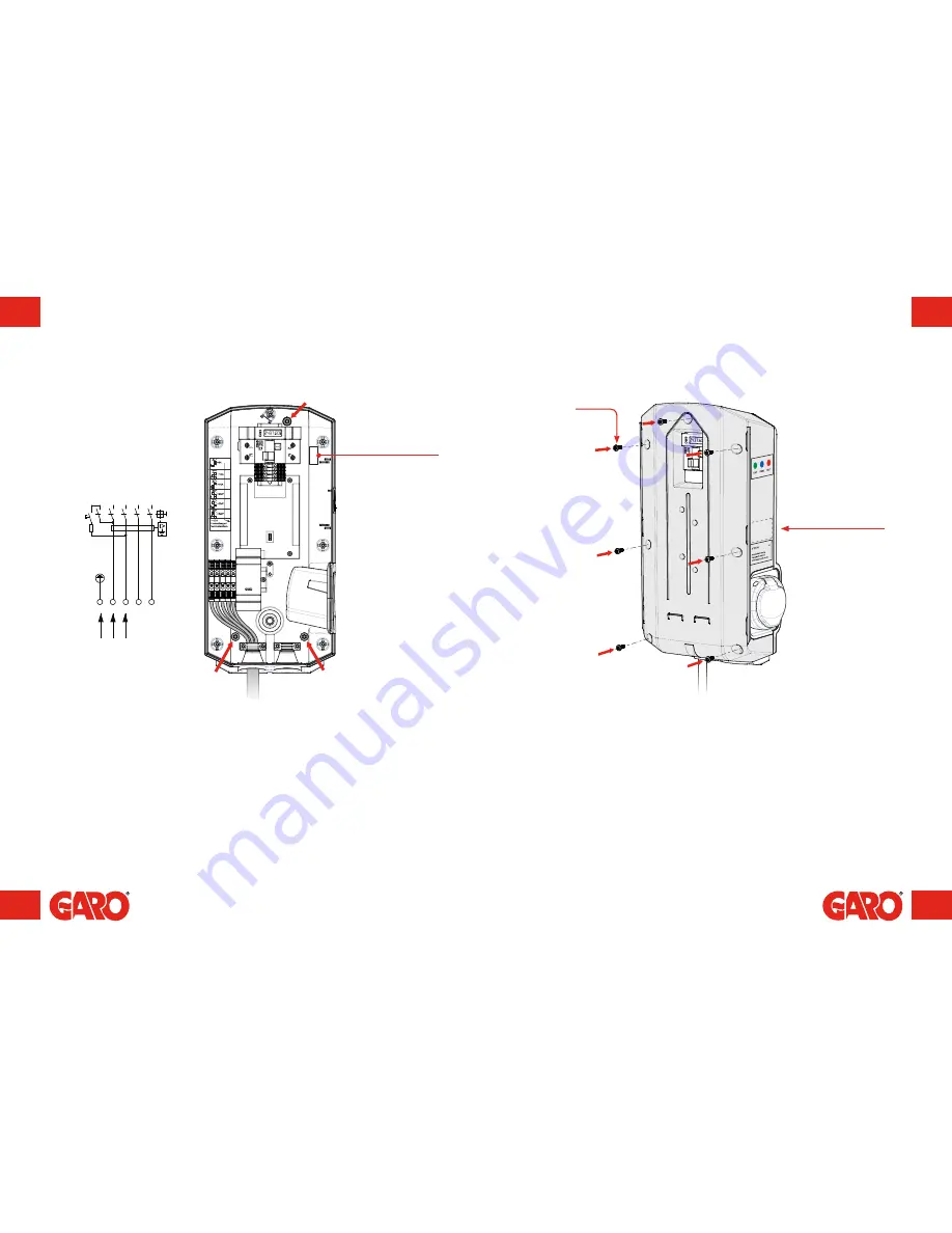
(figure 7)

language labels

are placed on the side

(figure 8)

Serial no./SSID 
password 
(Wi-Fi version only)

For incoming single-phase supply 
(16A, 240V or 32A, 240V) on 
a three-phase GLB, the incoming 
phase is channelled to connection 
block L1.

8.

Screw the base box onto the wall using three screws suitable for the wall 
surface. See the red arrows in figure 6.

9.

Feed the cable through the cable inlet.

10. Connect the cable onto the connection blocks. The connection blocks are 

compatible with cables measuring 1.5 mm²–6 mm², and up to 10 mm² in the 
32A Wallbox.

11. Does the charging current need to be reduced? Refer to section: Reducing 

charging current.

12. Carefully place the cover in position from the front. Ensure the inserts on the right 

hand side fit into the groove and that it looks correct. If the charger has Wi-Fi 
connectivity, verify that the SSID numbers on the cover and base plate match.

13. Securely attach the cover using the seven screws.
14. Verify that the personal protective/residual-current circuit breaker is switched on.

T20

Содержание GLB

Страница 1: ...EN GARO GLB Wallbox Assembly instructions Instructions of use EN 380177 2...

Страница 2: ...cable and connector type 1 or 2 with type 2 socket figure 3 figure 2 I A Front cover B Cover C Base box D Indication light E Key F Connector type 1 or 2 G Type 2 socket H Personal protective circuit...

Страница 3: ...Load balancing for multiple chargers in group 22 Load balancing settings in the web interface 24 Instructions for users 28 Charging e vehicles 29 Resetting Relocation 31 GLB Wi Fi Master 32 Connectin...

Страница 4: ...your e vehicle using the GARO Wallbox This document contains general descriptions which have been verified for their accuracy at the time of printing However as GARO is committed to the pursuit of co...

Страница 5: ...tory default current A 16A Factory default SW3 SW3 Reset button Press down 3 sec to reset WiFi back to default Access Point mode See label behind sliding front cover for SSID name and password Congrat...

Страница 6: ...mbly instructions for fitters Contents of the box EN GARO Wallbox Assembly instructions User Instructions EN 380175 3 Contents of the box Language labels GBL Wallbox Keys Drill template see the back o...

Страница 7: ...late to the wall where the charger will be installed Suitable height see Technical data on page 45 4 Drill mark in accordance with the instructions on the drill template 5 Unlock the front cover with...

Страница 8: ...wall surface See the red arrows in figure 6 9 Feed the cable through the cable inlet 10 Connect the cable onto the connection blocks The connection blocks are compatible with cables measuring 1 5 mm...

Страница 9: ...nstallation figure 9 figure 10 15 Re install the front cover by feeding it in from below 16 Lock the front cover with the key 17 Connect the power and ensure the indication light is constantly green 1...

Страница 10: ...n be reduced using the switches on the circuit board The supply voltage must be broken before the charging current is reduced The wallbox is equipped with a port where charging can be activated and de...

Страница 11: ...tripping When using a single phase wallbox a single phase energy meter must be installed to the phase to which the wallbox is connected Load balancing for individual chargers Example of installation...

Страница 12: ...low example the SW1 DIP 6 DIP switch is to be set to ON in wallboxes no 1 and 5 and OFF in the remaining boxes To verify that the master wallbox is defined as master ensure the SW1 switch DIP 5 is set...

Страница 13: ...ied out via the wallbox s web interface To connect a mobile phone tablet or computer to the wallbox see the section entitled Connecting to a Wi Fi access point AP The Load balancing meter connected Gr...

Страница 14: ...limitation B Set maximum current A or power kWh C In the case of a single phase charger if the charger is to be controlled by load balancing the phase assignation must be set Three phase chargers do...

Страница 15: ...inlet lock the cable As a result charging must be stopped before the cable is removed from the vehicle 4 When charging is completed ensure the cable has been hung up If your wallbox is equipped with...

Страница 16: ...for resetting relocation 1 Unlock the front cover with the key provided 2 Open the front cover A by sliding it downwards 3 Reset the breaker H latch During relocation press the breaker s test button...

Страница 17: ...puter see image to the right Connect to the wallbox s wireless network and enter the password 4 Launch the browser on your device The device will display the wallbox s website automatically To connect...

Страница 18: ...into three sections Home Status current measurement values control and scheduled control Energy Display of energy over time Settings The wallbox s settings settings and management of charging current...

Страница 19: ...elect the day and start stop time 3 Click Book 4 Check that the correct time has been booked in the schedule To remove scheduled times click on the time to be removed indicated in blue text Scheduled...

Страница 20: ...display C Total energy consumption for the month A Information about charger B Limitation of charging current See section entitled Limiting charging current C Choice of communication connection See se...

Страница 21: ...of charging current for a fixed period A B Connect charger to a local network via Wi Fi The wallbox will attempt to connect to the specified Wi Fi network If the data entered is incorrect or the conne...

Страница 22: ...EN GLB WIFI Master only Enter the serial no SSID and password appearing on the label on the cover Launch chargebox garo se in your browser GLB WIFI Master Connect charger to a local network via Wi Fi...

Страница 23: ...ivating RFID GLB WIFI Master Activating Deactivating RFID figure 34 Activating RFID To activate the RFID reader check the box labelled Request RFID when connecting and click Save Deactivating RFID To...

Страница 24: ...ield to be used for entering the name of the person using the tag for example When RFID is activated a registered RFID tag must be held out in order to activate the charger after the vehicle has been...

Страница 25: ...kg including socket 3 8 4 1 kg including cable and connector single phase 5 4 kg including cable and connector three phase Technical data Troubleshooting Instructions Troubleshooting Indication Type o...

Страница 26: ...50 51 EN EN 205 124 422 Dimensional drawing Dimensional drawing figure 33...

Страница 27: ...GARO AB Box 203 SE 335 25 Gnosj Phone 46 0 370 33 28 00 Fax 46 0 370 33 28 50 info garo se garo se...

Отзывы: