background image

190-00906-00

GTX 33 Installation Manual

Rev. F

Page 4-11

4.7 RS-232 Input/Output, Software Update Connections

When the GTX 33 is installed in a system other than a Garmin Integrated Flight Deck an optional RS-232 
serial data connector should be installed in the aircraft for future software upgrades, negating the need to 
remove the transponder from the aircraft. The connector can be mounted anywhere convenient for access, 
such as under the instrument panel, on a remote avionics shelf next to the unit or in the instrument panel 
itself. Be sure to label the connector for Software Update. Do not include the Test Mode Select switch in 
the aircraft. See Figure 4-2 for software update connections.

If the GTX 33 installation interfaces with a GNS 480 (CNX80) in the aircraft, the GNS 480 (CNX80) must 
be turned off during GTX 330 software upload, due to loading of RS-232 port 1.

NOTE

The installation of an optional software upgrade connector is highly recommended. If the 
connector is wired in the aircraft, transponder removal and reinstallation for software 
upgrade is not required.

CAUTION

If the unit is removed from the aircraft and operated, always connect J3302, (and J3303 
for GTX 33D) to an antenna or a 50 

, 5-Watt load. The GTX 33 transmits Mode S 

acquisition squitter replies about once per second whether interrogations are received or 
not.

Beginning with software version 3.06, the GTX 33 software can be updated in the Configuration mode as 
well as in Test mode. Updating software in Configuration mode does not require the TEST MODE 
SELECT switch.

Figure 4-2. GTX 33 Software Update Connections

Содержание GTX 33

Страница 1: ...GTX 33 Installation Manual Transponder ...

Страница 2: ...rive or other electronic storage medium to be viewed and to print one copy of this manual or of any revision hereto provided that such electronic or printed copy of this manual or revision must contain the complete text of this copyright notice and provided further that any unauthor ized commercial distribution of this manual or any revision hereto is strictly prohibited Garmin International Inc 1...

Страница 3: ...ange F 2 2 2 2 1 Added new back plate assemblies 2 6 2 4 1 Corrected Cable Routing Considerations Section C 2 and C 4 C Added new installation drawings with TNC connectors Section Page Range Table of Contents i vi Section 1 1 1 1 12 Section 2 2 1 2 8 Section 3 3 1 3 6 Section 4 4 1 4 10 Appendix A A 1 A 2 ...

Страница 4: ... required to be included on any and all reproductions in whole or in part of this manual WARNING This product its packaging and its components contain chemicals known to the State of California to cause cancer birth defects or reproductive harm This Notice is being provided in accordance with California s Proposition 65 If you have any questions or would like additional information please refer to...

Страница 5: ...Interface Summary 1 4 1 7 Technical Specifications 1 5 1 8 License Requirements 1 7 1 9 Certification 1 8 1 10 Reference Documents 1 11 1 11 Limited Warranty 1 12 2 INSTALLATION OVERVIEW 2 1 2 1 Introduction 2 1 2 2 Installation Materials 2 1 2 3 Installation Considerations 2 3 2 4 Cabling and Wiring 2 5 2 5 Installation Approval Considerations for Pressurized Aircraft 2 6 ...

Страница 6: ... OF STRUCTURES A 1 A 1 Static Test Loading A 1 A 2 Determining Static Load Capability A 1 Appendix B VERSION 1 ADS B FIELD APPROVAL COMPLIANCE MATRIX B 1 Appendix C OUTLINE AND INSTALLATION DRAWINGS C 1 Appendix D INTERCONNECT DRAWINGS D 1 ...

Страница 7: ...subject to change without notice Authorized Garmin Sales and Service Centers are encouraged to access the most up to date bulletin and advisory information on the Garmin web site at www garmin com using their Garmin provided user name and password GTX 33 P N 011 00779 00 011 00779 20 HARDWARE MOD LEVEL HISTORY GTX 33 P N 011 00779 10 011 00779 30 HARDWARE MOD LEVEL HISTORY MOD LEVEL SERVICE BULLET...

Страница 8: ...GTX 33 P N 011 00779 50 011 00779 70 HARDWARE MOD LEVEL HISTORY MOD LEVEL SERVICE BULLETIN NUMBER SERVICE BULLETIN DATE PURPOSE OF MODIFICATION None at this time ...

Страница 9: ...tible control display units such as the Garmin GNS 480 CNX80 GTN 6XX 7XX and GMX 200 MX20 Multifunction Display MFD 1 2 Equipment Description The Garmin GTX 33 rack mounted Mode S Transponder is a radio transmitter and receiver that operates on radar frequencies receiving ground radar and TCAS interrogations at 1030 MHz and transmitting a coded response of pulses on a frequency of 1090 MHz The GTX...

Страница 10: ...ee JAA NPA 20 12a to ground radar systems Compliance with Enhanced Surveillance may require additional interface between aircraft systems and the GTX 33 The GTX 33 and GTX 33D differ from the GTX 33H and GTX 33DH in the qualified DO 160 vibration categories See the GTX 33 Environmental Qualification Form 005 00131 03 for details 1 3 ADS B Capabilities The Extended Squitter Enabled GTX 33 provides ...

Страница 11: ...re update is available from Garmin 2 Installers may obtain a Supplemental Type Certificate STC for the GTX 33 with the Version 1 ADS B Extended Squitter activated 3 Installers may obtain a field approval with the Version 1 ADS B Extended Squitter activated EASA AMC 20 24 compliance matrix provided in Appendix B may be used to assist installers in showing compliance to the AMC requirements This dat...

Страница 12: ...raft power input 14 28 Vdc Remote power turn on Serial airdata or GPS groundspeed input Serial altitude input Reduces wire count vs parallel wire gray code altimeter interface Software update input Supports Comm A and Comm B protocol Temperature Altitude Hold and Density Altitude Digitally recorded voice and discrete warning annunciator activated by Altitude Hold when limits are exceeded Diversity...

Страница 13: ...23 Environmental Qualification Form Garmin part number 005 00131 03 To obtain a copy of this form see the dealer OEM portion of the Garmin web site www garmin com 1 7 1 Physical Characteristics Table 1 2 GTX 33 Physical Characteristics Characteristic Specification Modular Rack Width 1 72 Inches 44 mm Modular Rack Height 6 30 Inches 160 mm Modular Rack Weight 0 4 lbs 0 18 kg Stand Alone Rack Width ...

Страница 14: ... ED 73B Unit Software RTCA DO 178B Level C D refer to Section 1 9 1 for specific applicability Complex Electronic Hard ware RTCA DO 254 Level C refer to Section 1 9 1 for specific applicability FCC Authorization Emission Designator 12M0M1D Temperature Range 45 C to 70 C continuous operation Altitude 55 000 Feet Transmitter Frequency 1090 MHz 1 MHz Transmitter Power 125 Watts minimum 250 Watts nomi...

Страница 15: ...specific details on whether a particular installation is exempt from licensing please visit the FCC web site http wireless fcc gov aviation Table 1 4 GTX 33 Power Requirements Characteristic Specification Input Voltage 14 28 Vdc See the Environmental Qualification Form for details on surge ratings and minimum maximum operating voltages Power Input 22 Watts Typical 45 Watts Maximum Maximum Full TSO...

Страница 16: ...e installing this article either on or within a specific type or class of aircraft to determine that the aircraft installation conditions are within the TSO standards TSO articles must have separate approval for installation in an aircraft The article may be installed only if performed under 14 CFR part 43 or the applicable airworthiness requirements ...

Страница 17: ... 006 B0172 01 Rev except 006 B0172 01 Rev A v1 00 Traffic Information Service TIS RTCA DO 239 Air Traffic Control Radar Beacon System Mode Select ATCRBS MODE S Airborne Equipment ETSO 2C112b 2C112b Class 1 Level 2s 006 B0172 01 Rev B v3 00 through 006 B0172 01 Rev U v5 01 2C112b Level 2es All 006 B0172 01 Rev except Extended Squitter Automatic Dependent Surveillance Broadcast ADS B and Traffic Inf...

Страница 18: ...U SW Part Number Air Traffic Control Radar Beacon System Mode Select ATCRBS MODE S Airborne Equipment TSO C112 Class 2A All 006 B0172 01 Rev Traffic Information Service TIS RTCA DO 239 Air Traffic Control Radar Beacon System Mode Select ATCRBS MODE S Airborne Equipment ETSO 2C112b 2C112b Class 1 Level 2s 2C112b Level 2es Extended Squitter Automatic Dependent B0 ...

Страница 19: ... ETSO Deviations TSO ETSO Deviation TSO C112 1 Garmin was granted a deviation from TSO C112 to use RTCA DO 178B instead of RTCA DO 178A 2 Garmin was granted a deviation from TSO C112 to use RTCA DO 160D instead of RTCA DO 160B 3 Garmin was granted a deviation from TSO C112 to use RTCA DO 181C instead of RTCA DO 181 TSO C166 1 Garmin was granted a deviation from TSO C166 to use RTCA DO 160D instead...

Страница 20: ...n materials or workmanship iii damage caused by accident abuse misuse water flood fire or other acts of nature or external causes iv damage caused by service performed by anyone who is not an authorized service provider of Garmin or v damage to a product that has been modified or altered without the written permission of Garmin In addition Garmin reserves the right to refuse warranty claims agains...

Страница 21: ...be found useful for making retro fit installations that comply with FAA regulations Refer to the G1000 System Installation Manual Garmin part number 190 00303 00 for further details on the mechanical aspects of the G1000 system rack For installation in an aircraft using the remote mounted stand alone rack refer to Appendix C for rack drawings and dimensions 2 2 Installation Materials The GTX 33 is...

Страница 22: ...GTX 33 Accessories Item Garmin Catalog Part Number Modular Install Rack GTX 33 GTX 33D 115 00438 00 For use with GTX 33 and GTX 33D G1000 Nutplate Kit 011 00915 01 preferred or 011 01148 01 Or GTX 33 GTX 33D Stand Alone Install Rack Alternate Configuration 115 00629 00 For use with GTX 33 and GTX 33D Or GTX 33H GTX 33DH Stand Alone Install Rack 011 02422 00 For use with GTX 33H and GTX 33DH ...

Страница 23: ...wing in Appendix C for more detail 4 ea for mounting of the remote stand alone rack for GTX 33H and GTX 33DH Encoding Altitude Digitizer For GNS 480 CNX80 GTN 6XX 7XX and GMX 200 MX20 installation Use encoding altimeter manufacturer s instructions The Garmin GAE 43 Garmin P N 013 00066 00 can provide altitude data in either serial or parallel gray code format 2 3 Installation Considerations In a G...

Страница 24: ... a second diversity antenna is installed in the aircraft considerations for its mounting should be made as outlined in Figure 2 1 The antenna installation should be installed in accordance with AC 43 12 2A Chapter 3 Note that penetration of the pressure vessel on the pressurized aircraft requires additional data not contained in this manual See Section 2 5 ...

Страница 25: ...abling and routing near aircraft control cables The GTX 33 and GTX 33D back plate assemblies utilize BNC type bayonet connection coaxial connectors The GTX 33H and GTX 33DH back plate assemblies utilize TNC type threaded connection coaxial connectors The following table lists examples of the recommended antenna cable vendors and the type of cable to be used for specific lengths of cable Any cable ...

Страница 26: ...s incorporate alteration penetration of the cabin pressure vessel by connector holes and or mounting arrangements Use of existing bulkhead connectors previously approved by other means is permissible without additional approval For needed engineering support pertaining to the design and approval of such pressurized aircraft antenna installations it is recommended that the installer proceed accordi...

Страница 27: ...ote racks can be installed in a variety of locations such as the electronics bay under a seat or on an avionics shelf behind the rear baggage area Refer to Figure 2 5 for suggested location Leave sufficient clearance between the GTX 33 and any obstruction Install the rack in accordance with AC 43 13 2B Chapter 2 Communication Navigation and Emergency Locator Transmitter System Installations The ra...

Страница 28: ......

Страница 29: ......

Страница 30: ......

Страница 31: ... and file a claim To justify a claim save the original shipping container and all packing materials Do not return the unit to Garmin until the carrier has authorized the claim Retain the original shipping containers for storage If the original containers are not available a separate cardboard container should be prepared that is large enough to accommodate sufficient packing material to prevent mo...

Страница 32: ...ssociated hardware are supplied with the connector kit See Appendix D for examples of interconnect wiring diagrams Construct the actual harnesses in accordance with the aircraft manufacturer authorized interconnect standards CAUTION Check wiring connections for errors before inserting the GTX 33 into the rack Incorrect wiring could cause internal component damage Table 3 1 Pin Contact Part Numbers...

Страница 33: ...allations To assemble the backshell and grounding system refer to the instructions provided in the G1000 System Installation Manual 190 00303 00 as well as the SPIDER Installation Instructions 190 00313 03 and Shield Block Installation Instructions 190 00313 09 Non G1000 Installations GTX 33 installations mounted as a remote transponder system the connector and backshell assembly is shown below Re...

Страница 34: ...5 Backshell Lid Provides access when servicing the connector ...

Страница 35: ... 1 5 1 identifies the weight of the new GTX 33 equipment and Figure C 1 in Appendix C shows the center of gravity 3 5 Electrical Load Analysis An electrical load analysis should be completed on each aircraft prior to installation in accordance with AC43 13 1B Chapter 11 Use the following values for computation 3 6 Final Installation For final installation and assembly refer to the outline and inst...

Страница 36: ...c aircraft and are typically contained within the file named GTX1 However the aircraft registration number must be entered manually The PFD serves as the graphics user interface to the installer configuring the system For basic configuration information refer to the G1000 Line Maintenance and Configuration Manual Garmin part number 190 00303 04 For actual aircraft installation checkout use only ai...

Страница 37: ...endix F of 14 CFR Part 43 to AC 43 6B and or other appropriate regulations The test is typically done as a ramp test using a transponder ramp test set such as the TIC TR 220 IFR ATC 601 or other suitable Mode S transponder test set Self Test Verify that the unit does not display a failure indication when turned on Altitude Input Verify that the displayed altitude matches pressure altitude at 29 92...

Страница 38: ...3 8 Continued Airworthiness Test according to Title 14 CFR 91 411 and 91 413 as well as Part 43 Appendix F Other than for regulatory checks maintenance of the GTX 33 is on condition only ...

Страница 39: ...4 SYSTEM INTERCONNECTS 4 1 Pin List 4 1 1 P3301 Connector Figure 4 1 View of J3301 connector from back of unit Table 4 1 P3301 Pin List Pin Pin Name I O 1 RESERVED In 2 ALTITUDE A1 In 3 ALTITUDE C2 In ...

Страница 40: ...29 IN 3 A In 27 POWER GROUND 28 ARINC 429 OUT 2 B Out 29 ARINC 429 IN 3 B In 30 ARINC 429 OUT 2 A Out 31 EXTERNAL SUPPRESSION I O I O 32 ARINC 429 IN 1 A In 33 ARINC 429 IN 2 A In 34 ARINC 429 OUT 1 B Out 35 ARINC 429 IN 1 B In Table 4 1 P3301 Pin List Pin Pin Name I O ...

Страница 41: ...s Active Low Ground to activate 55 NOT USED 56 AIRCRAFT POWER 2 In 57 NOT USED 58 SIGNAL GROUND 59 NOT USED 60 AIRCRAFT POWER 2 In 61 NOT USED 62 SWITCHED POWER OUT Out Table 4 1 P3301 Pin List Pin Pin Name I O ...

Страница 42: ...a remote digital altitude encoder Refer to Figure D 1 and D 2 for power interconnections 4 2 1 Aircraft Power Table 4 2 Aircraft Power Pin Name Connector Pin I O AIRCRAFT POWER 1 P3301 21 In AIRCRAFT POWER 1 P3301 42 In AIRCRAFT POWER 2 P3301 56 In AIRCRAFT POWER 2 P3301 60 In SWITCHED POWER OUT P3301 62 Out XPDR REMOTE POWER OFF P3301 54 In POWER GROUND P3301 27 POWER GROUND P3301 43 ...

Страница 43: ... The GTX 33 contains internal altitude code line isolation diodes to prevent the unit from pulling the encoder lines to ground when the transponder is turned off If two separate altitude encoders are connected to the GTX 33 one providing parallel gray code and the other serial data the unit selects only one for use at a time with serial data input receiving the highest priority For altitude encode...

Страница 44: ...or Pin I O ALTITUDE D4 P3301 11 In ALTITUDE A1 P3301 2 In ALTITUDE A2 P3301 4 In ALTITUDE A4 P3301 5 In ALTITUDE B1 P3301 7 In ALTITUDE B2 P3301 9 In ALTITUDE B4 P3301 10 In ALTITUDE C1 P3301 8 In ALTITUDE C2 P3301 3 In ALTITUDE C4 P3301 6 In ALTITUDE COMMON P3301 50 ...

Страница 45: ...raft avionics system Depending on system configuration the Garmin Integrated Flight Deck may not use these inputs as many functions are received from the GIA 63 in RS 232 format 4 5 1 Discrete Outputs External suppression should be connected if a DME is installed in the aircraft avionics system The GTX 33 suppression I O pulses may not be compatible with all models of DME Known incompatible units ...

Страница 46: ...CNX80 Installation Manual MX20 Installation Manual or appropriate GTN 6XX 7XX Installation Manual for TIS configuration An AUDIO MUTE SELECT mute switch may be used to control TIS audio alerts TIS Traffic Mute must be clearly marked with MUTE ON MUTE OFF or TIS Audio ON Audio OFF labels The muting feature may be enabled through a Multi Function display In order to prevent inadvertent muting the st...

Страница 47: ...NC 429 OUT 1B P3301 34 Out ARINC 429 IN 1A P3301 32 In ARINC 429 IN 1B P3301 35 In ARINC 429 IN 2A P3301 33 In ARINC 429 IN 2B P3301 36 In ARINC 429 OUT 2A P3301 30 Out ARINC 429 OUT 2B P3301 28 Out ARINC 429 IN 3A P3301 26 In ARINC 429 IN 3B P3301 29 In ARINC 429 IN 4A P3301 48 In ARINC 429 IN 4B P3301 49 In ...

Страница 48: ... Pressure Altitude in feet set to 29 92 Hg 1013 25 mb 100 ms 204 Barometric Corrected Altitude feet 100 ms 206 Indicated Air Speed knots 100 ms 210 True Air Speed knots 100 ms 211 Total Air Temperature degrees 100 ms 213 Static Air Temperature degrees 100 ms 306 Joystick Lat 500 ms 307 Joystick Lon 500 ms 314 True Heading 100 ms 320 Magnetic Heading Degrees 100 ms 371 GA Equipment Identifier 500 m...

Страница 49: ...bel the connector for Software Update Do not include the Test Mode Select switch in the aircraft See Figure 4 2 for software update connections If the GTX 33 installation interfaces with a GNS 480 CNX80 in the aircraft the GNS 480 CNX80 must be turned off during GTX 330 software upload due to loading of RS 232 port 1 NOTE The installation of an optional software upgrade connector is highly recomme...

Страница 50: ......

Страница 51: ...ft structure in accordance with the methods outlined in AC 43 13 2B Chapter 2 After the structure is installed it should be tested as outlined in AC 43 13 2B Chapter 1 to verify that it is capable of supporting the required loads The GTX 33 installation must be capable of withstanding the Ultimate Load Factors listed in Table A 1 for at least 3 seconds in each direction specified without damage or...

Страница 52: ...ucture carefully If there has been damage or permanent deformation the structure is not suitable and must be replaced with one that is strong enough to withstand the test loads Examine all aircraft stringers bulkheads and skin surfaces which may have direct or indi rect contact with the fabricated shelf If it is determined that no damage or permanent deformation has occurred the structure is of su...

Страница 53: ...eferred to as Garmin GNS GTN equipment no additional data is required for the compliance matrix Compliance statements are pre populated for all aspects involving GNSS position source requirements If a non Garmin GPS position source is used the installer must 1 Determine the GPS position source is compliant with the ARINC 743A standard 2 Obtain and input the appropriate data into the compliance mat...

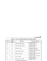
Страница 54: ...e ADS B System needs to meet the fol lowing surveillance data transmission requirements as a mini mum Section heading no compliance statement req d 3 7 1 A unique ICAO 24 bit aircraft address contained within each ADS B mes sage transmission Supported in all Mode S transmissions from the GTX 33 Aircraft address data is sourced from transponder internal configuration settings Supported in BDS 0 5 A...

Страница 55: ...settings 8 7 1 Special Position Identification SPI Supported in BDS 6 5 Aircraft Operational Status SPI data is sourced from transponder internal IDENT status The IDENT function is controlled via GTX 33 control and display device Supported in BDS 6 1 Table B 1 Version 1 ADS B Field Approval Compliance Matrix Item AMC Section AMC Item Compliance Summary ...

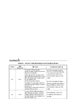
Страница 56: ...n line with ED 126 Section 3 4 Appendix 3 provides a summary for information purposes See items below compiled from AMC 20 24 Appendix 3 Tables 14 8 1 Horizontal Position and Horizontal Position Quality Indicator s Requirement 10 5 fh Garmin GNS GTN Equipment GPS SBAS engine meets the 10 5 per hour requirement Other Table B 1 Version 1 ADS B Field Approval Compliance Matrix Item AMC Section AMC It...

Страница 57: ... The GPS SBAS engine meets the 2NM containment radius requirement under conditions of sufficient GPS satellite coverage Other Horizontal Position Source Integrity Source Failure This requirement is met by the GPS SBAS system and is not Table B 1 Version 1 ADS B Field Approval Compliance Matrix Item AMC Section AMC Item Compliance Summary ...

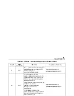
Страница 58: ...The GPS SBAS engine meets the 10 second time to alert requirement in all modes Other 22 8 1 Barometric Altitude Accuracy Appen dix 3 Table 3 Requirement as per the installed sensors refer to section 8 5 2 See response to Item 64 Table B 1 Version 1 ADS B Field Approval Compliance Matrix Item AMC Section AMC Item Compliance Summary ...

Страница 59: ...ontal position data source s to ADS B transmit data string encoding needs to be 10 5 fh refer also to Table 1 in Appendix 3 GTX 33 design assurance is Level C which satisfies the 10 5 flight hour requirement Garmin GNS GTN Equipment The GPS SBAS engine design assurance levels are qualified to Level B Other Table B 1 Version 1 ADS B Field Approval Compliance Matrix Item AMC Section AMC Item Complia...

Страница 60: ...Table 1 in Appendix 3 Garmin GNS GTN Equipment Total position data latency is 1 second GPS antenna signal to Time of Applicability 500 ms Position solution relayed to the transponder 200 ms Potential position solution update delay until the next solution over write is relayed to the transponder 300 ms given a 200 ms update rate Other Table B 1 Version 1 ADS B Field Approval Compliance Matrix Item ...

Страница 61: ...tatus 39 8 3 1 Quality indicator NACp Supported in BDS 6 5 Aircraft Operational Status 40 8 3 1 Quality indicator SIL Supported in BDS 6 5 Aircraft Operational Status 41 8 3 1 Version Indicator Supported in BDS 6 5 Aircraft Operational Status 42 8 3 1 Airborne Ground Velocity Supported in BDS 0 9 Airborne Velocity Table B 1 Version 1 ADS B Field Approval Compliance Matrix Item AMC Section AMC Item...

Страница 62: ...ontal position sources GTX 33 calculates DO 260A NIC using Horizontal Protection Limit HPL provided by the GPS position source per DO 260A GTX 33 calculates DO 260A NAC using Horizontal Figure of Merit HFOM provided by the GPS position source per DO 260A 46 8 3 5 In case of ED 102 DO 260 based ADS B transmit systems the NUC Quality Indicator value need to be encoded based on the integrity con tain...

Страница 63: ...ystem such as the GNSS space segment fall outside these airworthiness considerations Such external compo nents are assumed to operate in accordance with their specified nominal performance Nevertheless failures of the external data source components are required to be detected through on board monitoring as General information no compliance statement req d Table B 1 Version 1 ADS B Field Approval ...

Страница 64: ...nt posi tion source 55 8 4 5 If the integrity containment radius is not provided by the horizontal position data source the ADS B transmit sys tem may use other means to establish an appropriate integrity containment radius provided a requirements compliant integrity alert mechanism is available Garmin GNS GTN Equipment Not applicable Other 56 8 4 6 Use of GNSS Systems as Primary Position Data Sou...

Страница 65: ...he requirements for GPS as a Primary Means of Navigation for Oceanic Remote Operations per FAA Advisory Circular 20 138A Appendix 1 Other 60 8 4 7 Use of Alternative Compliant Position Data Sources As the ED 126 safety and performance assessments are based on the performance and characteris tics of GNSS systems for alternative position sources a Garmin GNS GTN Equipment Not applicable Other Table ...

Страница 66: ...h the pressure altitude information referenced to the standard pressure setting of 1013 25 hectopascals used on board the aircraft to adhere to the assigned flight profile ICAO Annex 10 Vol IV The Mode C altitude data reported by the GTX transponder is the same as the altitude used by the flight crew to adhere to the assigned flight profile Per the requirements of 14 CFR 91 411 a and Part 43 Appen...

Страница 67: ... take precedence General information no compliance statement req d 67 8 6 Aircraft Identification General information no compliance statement req d Identification needs to be provided to the ADS B transmit system so that the information is identical to the filed ICAO flight plan This information may be provided from Table B 1 Version 1 ADS B Field Approval Compliance Matrix Item AMC Section AMC It...

Страница 68: ...nsmit systems the discrete emergency code declaration capability should be integrated into the transponder func tionality and should be controlled from the transponder control panel The GTX 33 facilitates the transponder code entry function 74 8 9 Airworthiness Considerations regard ing Optional Provisions Section heading no compliance statement req d Garmin GNS GTN Equipment The Table B 1 Version...

Страница 69: ...er gency status discrete emergency code Not applicable GTX 33 uses ATC transponder based system 78 8 9 4 Flight Deck Control Capabilities OPTIONAL Section heading no compliance statement req d 79 8 9 4 1 Means should be provided to the flight crew to modify the Aircraft Identifica Flight ID may be manually set by the pilot depending on Table B 1 Version 1 ADS B Field Approval Compliance Matrix Ite...

Страница 70: ......

Страница 71: ...190 00906 00 GTX 33 Installation Manual Rev F Page C 1 APPENDIX C OUTLINE AND INSTALLATION DRAWINGS Figure C 1 GTX 33 in Modular Rack Outline Drawing ...

Страница 72: ...190 00906 00 GTX 33 Installation Manual Rev F Page C 2 APPENDIX C OUTLINE AND INSTALLATION DRAWINGS Figure C 2 GTX 33 G1000 Connector Rack Assembly Drawing ...

Страница 73: ...190 00906 00 GTX 33 Installation Manual Rev F Page C 3 APPENDIX C OUTLINE AND INSTALLATION DRAWINGS Figure C 3 GTX 33 Remote Stand Alone Rack Connector Assembly Sheet 1 of 2 ...

Страница 74: ...190 00906 00 GTX 33 Installation Manual Rev F Page C 4 APPENDIX C OUTLINE AND INSTALLATION DRAWINGS Figure C 4 GTX 33 Remote Stand Alone Rack Connector Assembly Sheet 2 of 2 ...

Страница 75: ...190 00906 00 GTX 33 Installation Manual Rev F Page C 5 APPENDIX C OUTLINE AND INSTALLATION DRAWINGS Figure C 5 GTX 33H Remote Stand Alone Rack Connector Assembly Sheet 1 of 2 ...

Страница 76: ...190 00906 00 GTX 33 Installation Manual Rev F Page C 6 APPENDIX C OUTLINE AND INSTALLATION DRAWINGS Figure C 6 GTX 33H Remote Stand Alone Rack Connector Assembly Sheet 2 of 2 ...

Страница 77: ...190 00906 00 GTX 33 Installation Manual Rev F Page D 1 APPENDIX D INTERCONNECT DRAWINGS Figure D 1 GTX 33 Typical Garmin Integrated Flight Deck Interconnect Wiring Diagram ...

Страница 78: ...190 00906 00 GTX 33 Installation Manual Rev F Page D 2 APPENDIX D INTERCONNECT DRAWINGS Figure D 2 GTX 33 to GNS 480 CNX 80 Simplified Interconnect Wiring Diagram ...

Страница 79: ...190 00906 00 GTX 33 Installation Manual Rev F Page D 3 APPENDIX D INTERCONNECT DRAWINGS Figure D 3 GTX 33 to MFD Simplified Interconnect Wiring Diagram ...

Страница 80: ...190 00906 00 GTX 33 Installation Manual Rev F Page D 4 APPENDIX D INTERCONNECT DRAWINGS Figure D 4 Dual GTX 33 to GNS 480 CNX80 Interconnect Wiring Diagram Single Altitude Encoder Sheet 1 of 2 ...

Страница 81: ...190 00906 00 GTX 33 Installation Manual Rev F Page D 5 APPENDIX D INTERCONNECT DRAWINGS Figure D 5 Dual GTX 33 to GNS 480 CNX80 Interconnect Wiring Diagram Single Altitude Encoder Sheet 2 of 2 ...

Страница 82: ...190 00906 00 GTX 33 Installation Manual Rev F Page D 6 APPENDIX D INTERCONNECT DRAWINGS Figure D 6 Dual GTX 33 to GTN 6XX 7XX Interconnect Wiring Diagram Encoding Altitude Connections Sheet 1 of 2 ...

Страница 83: ...190 00906 00 GTX 33 Installation Manual Rev F Page D 7 APPENDIX D INTERCONNECT DRAWINGS Figure D 7 Dual GTX 33 to GTN 6XX 7XX Interconnect Wiring Diagram Encoding Altitude Connections Sheet 2 of 2 ...

Отзывы: