background image

190-01007-C1

GTN Xi Part 23 AML STC Maintenance Manual

Rev. 1

Page 7-17

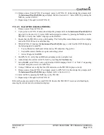
7.3.4 Transponder

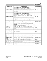
1. For remote transponders, configure transponder per Section 7.3.4.1.
2. Perform interface check per Section 7.3.4.2.

7.3.4.1 Remote Transponder Configuration

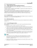
A remote transponder can be configured by the GTN Xi through RS-232 if a transponder is configured for 

one of the RS-232 ports. To configure the transponder, it must first be selected as 

Present

 and the type of 

transponder installed must be specified. To do this, access the 

Interfaced Equipment


page on the 

GTN Setup

 page. Next, go to the 

External Systems

 page and touch the 

XPDR

 key. This displays the 

XPDR( )

 page, which allows the remote transponder to be configured. The remote transponder should be 

configured in accordance with the installation manual for that specific transponder.

NOTE

If the GTN Xi controls any transponder (GTX 3XX/3XXR), then that transponder will boot 

into the same mode (Normal or Configuration) as the GTN Xi. 

NOTE

If the GTN Xi is not communicating with the GTX transponder, all of the editable fields for 

the setup items shown in the following sections will be dashed out. If the fields are dashed 

out, check the wiring and pin connections from the GTN Xi to the transponder. 

NOTE

The GTX 335R/345R must be configured through the GTX 3X5 Install Tool. Refer to 

GTX 3X5 TSO Installation Manual for more information.

NOTE

The GTN Xi can interface to the GTX 3XX; however, configuration of the panel-mounted 

GTX 3XX is not supported. These transponders should be configured per their installation 

manuals rather than through the GTN Xi. 

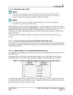
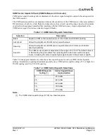
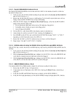
7.3.4.2 Transponder Interface Check

If the GTN Xi is interfaced to a GTX 32/33/3X5R remote transponder, or a GTX 3XX configured as a 

remote transponder, the following checks must be completed:

1. With the GTN Xi in Normal mode, and the transponder powered on, go to the home page and 

ensure there is not a red “X” over the transponder data field on the screen.

2. Check that a code can be entered into the Code field. Enter a code using the keypad and then touch 

the 

Enter

 key. Check that the code that was entered is displayed in the Transponder Data field.

3. If dual transponders are installed, select 

Transponder 2

 and perform steps 1 and 2 for the second 

transponder as well.

4. To verify wiring is not crossed, open the Transponder 1 circuit breaker and verify the 

Transponder 1 data field has a red “X”.

5. Repeat the steps 1 through 3 for GTN Xi #2.

Содержание GTN Xi Series

Страница 1: ...nce Manual Contains Instructions for Continued Airworthiness for STC SA02019SE D Aircraft make model registration number and serial number along with the applicable STC configuration information must...

Страница 2: ...mercial distribution of this manual or any revision hereto is strictly prohibited Adobe is a registered trademark of Adobe Systems Incorporated All rights reserved 2020 The Bluetooth word mark and log...

Страница 3: ...190 01007 C1 GTN Xi Part 23 AML STC Maintenance Manual Rev 1 Page B RECORD OF REVISIONS Revision Revision Date Description 1 01 03 20 Initial release...

Страница 4: ...State of California to cause cancer birth defects or reproductive harm This notice is being provided in accordance with California s Proposition 65 If you have any questions or would like additional...

Страница 5: ...g Test 4 6 4 6 Transient Voltage Suppressor TVS If Installed 4 9 5 TROUBLESHOOTING 5 1 5 1 GTN Xi General Troubleshooting 5 2 5 2 GTN Xi Failure Annunciations 5 6 5 3 GTN Xi System Messages 5 7 5 4 Fl...

Страница 6: ...01007 C1 GTN Xi Part 23 AML STC Maintenance Manual Rev 1 Page iii 7 5 Configuration Module 7 23 8 RETURN TO SERVICE PROCEDURE 8 1 8 1 Maintenance Records 8 1 APPENDIX A AIRCRAFT SPECIFIC INFORMATION...

Страница 7: ...Chart Configuration Page 3 16 Figure 3 15 COM Transmit Power Configuration Page 3 16 Figure 3 16 Weather Radar Page 3 17 Figure 3 17 Search and Rescue Configuration Page 3 18 Figure 3 18 GTN 6XX Xi an...

Страница 8: ...shooting Guide 5 18 Table 5 11 TAWS Alert Troubleshooting Guide 5 20 Table 5 12 Third Party Sensor Alert Troubleshooting Guide 5 21 Table 5 13 Flight Stream Troubleshooting 5 22 Table 5 14 GMA 35 Trou...

Страница 9: ...C1 GTN Xi Part 23 AML STC Maintenance Manual Rev 1 Page 1 1 1 INTRODUCTION 1 1 Content Scope and Purpose 1 2 1 2 Organization 1 2 1 3 Definitions and Abbreviations 1 3 1 4 Publications 1 4 1 5 Distrib...

Страница 10: ...35c Flight Stream 210 and Flight Stream 510 Section 4 Instructions for Continued Airworthiness Provides Instructions for Continued Airworthiness of the GTN Xi GMA 35 35c Flight Stream 210 and Flight...

Страница 11: ...ment System RX Receive EHSI Electronic Horizontal Situation Indicator SAR Search and Rescue FIS B Flight Information Services Broadcast SBAS Satellite Based Augmentation System FPGA Field Programmable...

Страница 12: ...el Garmin dealers may obtain the latest revision of this document at the Garmin Dealer Resource website Dealers are notified of manual revision changes via a Garmin Service Bulletin Owner operators ma...

Страница 13: ...age 2 1 2 SYSTEM DESCRIPTION 2 1 Equipment Descriptions 2 2 2 1 1 GTN Xi Navigators and GMA 35 2 2 2 1 2 NAV Antenna Cable Splitter 2 3 2 1 3 NAV Antenna Cable Diplexer 2 3 2 2 Backplate Connectors 2...

Страница 14: ...834 986 pixel color LCD touchscreen The GTN 725Xi is a GPS SBAS unit that meets the requirements of TSO C146c and may be approved for IFR en route terminal oceanic non precision and precision approach...

Страница 15: ...data card slot The Flight Stream 510 interfaces to the GTN Xi by replacing the front loaded data card to allow wireless database synchronization with PEDs Synchronized information is then disseminated...

Страница 16: ...TN Xi Part 23 AML STC Maintenance Manual Rev 1 Page 2 4 2 2 Backplate Connectors Figure 2 1 GMA 35 Connector Layout Detail Rear View Figure 2 2 GMA 35c Bluetooth Connector Layout Detail Front View J35...

Страница 17: ...190 01007 C1 GTN Xi Part 23 AML STC Maintenance Manual Rev 1 Page 2 5 Figure 2 3 GTN 6XX Xi Connector Layout Detail Rear View Figure 2 4 GTN 7XX Xi Connector Layout Detail Rear View...

Страница 18: ...erializer or fuel air data computers Autopilot EFIS displays EHSI displays IRU AHRS Navigation indicators Weather traffic terrain systems DME CDI HSI source selection annunciators TAWS annunciator pan...

Страница 19: ...COM REMOTE TRANSFER SWITCH COM REMOTE TUNE UP COM REMOTE TUNE SWITCHES COM REMOTE TUNE DOWN COM AUDIO VLOC AUDIO POWER GROUND AIRCRAFT POWER GROUND VOR OBI NAV ARINC 429 IN NAV ARINC 429 OUT POWER GRO...

Страница 20: ...1 Page 3 1 3 CONTROL AND OPERATION 3 1 GTN Xi Normal Mode Overview 3 2 3 2 GTN Xi Configuration Mode Overview 3 3 3 2 1 Updates 3 4 3 2 2 System Information 3 11 3 2 3 GTN Setup 3 12 3 2 4 GTN Options...

Страница 21: ...der Panel Controls Annunciations Locking Screw SD Card Volume Squelch and NAV ID Function Keys Active COM Frequency Standby COM Frequency Message Annunciation Photocell HOME key Direct To Key Large an...

Страница 22: ...OME key when the display activates and Garmin appears fully lit on the screen The Configuration mode home page is the first page displayed For detailed information regarding how to configure the GTN X...

Страница 23: ...le Software SD Card P N 010 01000 00 in conjunction with a GTN xi software application downloaded from the Dealer Resource Center on Garmin s website As an alternative a pre programmed software loader...

Страница 24: ...the correct Software Loader Image part number 3 Run the executable file The window shown in Figure 3 4 will appear Click Setup Figure 3 4 Software Update Installer 4 The window shown in Figure 3 5 wi...

Страница 25: ...in Figure 3 6 Click Next when finished Figure 3 6 Software Loader Card License Agreement 7 Click Find Drive or select the correct drive from the drop down menu Click Next CAUTION In order to create a...

Страница 26: ...created Figure 3 8 Software Loader Card Progress Window 9 After the card has been created the window shown in Figure 3 9 will appear Click Finish to complete the update process Figure 3 9 Software Lo...

Страница 27: ...he available GTN Xi software updates are displaying by ensuring that GTN Software Updates key is highlighted in the upper left corner upper right for GTN 6XX Xi of the display 7 To update the GTN Xi w...

Страница 28: ...7 To update the GMA 35 with all available software touch Select All Alternatively individual updates can be manually selected by touching them A green checkmark will appear when selected 8 Touch the U...

Страница 29: ...e the GMA 35 circuit breaker is closed 5 Select all GMA 35 Boot Block updates 6 To begin the software update touch the Update key on the bottom of the display 7 The GTN Xi will display the prompt Star...

Страница 30: ...tion page displays the unit type serial number and System ID for the GTN Xi unit It contains the software and hardware versions of the Main I O Display Keypad LED GPS WAAS COM and NAV boards System in...

Страница 31: ...speeds are set from this configuration page RS 232 Configures the RS 232 input and output ports HSDB Ethernet Configures which Ethernet ports are connected Interfaced Equipment Configures which LRUs a...

Страница 32: ...the RX squelch volume Mic 1 Gain and sidetone volume The COM page is only available on the GTN 635Xi 650Xi 750Xi VOR LOC GS Checks the CDI outputs from the VOR LOC GS receiver and the OBS resolver inp...

Страница 33: ...tion Manual for additional requirements and checkout procedures This manual only describes the necessary steps to re enable the feature for existing installations All re enablements use the feature en...

Страница 34: ...osing the circuit breaker to the GTN Xi while holding the HOME key 4 Navigate to the Terrain Configuration page from the GTN Options page Touch the TAWS B key 5 When the TAWS feature is activated the...

Страница 35: ...hartView feature is activated the ChartView key will be lit green as shown in Figure 3 14 3 2 4 3 COM Transmit Power GTN 635Xi 650Xi 750Xi Only When the optional 16W COM power is configured the GTN Xi...

Страница 36: ...0878 46 dual install is needed for Ground Clutter Suppression To enable Radar Turbulence Detection 1 Power off the GTN Xi by opening the NAV GPS circuit breaker 2 Remove the database SD card from the...

Страница 37: ...ard slot and insert the Search and Rescue Enablement Card P N 010 00878 03 3 Power on the GTN Xi in Configuration mode by applying power i e closing the circuit breaker while holding the HOME key 4 Na...

Страница 38: ...SSM Data and SDI for the selected ARINC 429 input port The data log can be paused by toggling the Pause Unpause key Clear the data log by touching the Clear Log key Serial Inputs Displays the serial d...

Страница 39: ...ne can be reset on this page Temps Displays the current minimum maximum and average board temperatures for the LED Board Main Board Display Interface Board GPS WAAS Board COM Board and COM Oscillator...

Страница 40: ...pdating the database on the card and re inserting the card Databases can also be updated using a Flight Stream 510 wireless data card and a portable device When powering on in Normal mode with a Fligh...

Страница 41: ...5 1 GTN Xi Bonding Check Metallic or Tube and Fabric Aircraft 4 6 4 5 2 GTN Xi Bonding Check Composite Aircraft 4 6 4 5 3 GMA 35 Bonding Check Metallic or Tube and Fabric Aircraft 4 7 4 5 4 GMA 35 Bon...

Страница 42: ......

Страница 43: ...Condition Battery Replacement The GTN Xi has an internal keep alive battery that will last about 10 years The battery is used for GPS system information Regular planned replacement is not necessary Th...

Страница 44: ...GMA 35 if installed Flight Stream 210 if installed Flight Stream 510 if installed switches and wiring harnesses should be inspected to ensure continued integrity of the installation These items must...

Страница 45: ...c Bluetooth antenna mount ensure the hook and loop bond is firm If the hook and loop fastener is worn replace it Flight Stream 210 If the Flight Stream 210 is installed and screws are not securely att...

Страница 46: ...TN Xi rack clean the attachment points with a bonding brush at both the rack and the aircraft and re attach the rack to the rails in the panel Measure the resistance between the mounting rack and near...

Страница 47: ...GTN 7XX Xi unit 2 Remove the GMA 35 unit from the mounting rack 3 Remove backplate assembly from the rack 4 Measure the resistance between the mounting rack and nearby exposed portion of aircraft meta...

Страница 48: ...bonding strap to the aircraft ground plane and torque to 12 to 15 in lbf Measure the resistance between the Flight Stream 210 connector and aircraft structure ensuring that the resistance is less tha...

Страница 49: ...TVS on the GTN Xi power inputs the following steps should be followed 1 Remove the GTN Xi unit as described in Section 6 1 2 Open the GTN Xi unit s circuit breaker and use a multimeter to perform a d...

Страница 50: ...ck lead on the connector socket contact i If the diode drop is outside of the above range replace the TVS diode corresponding to the contact being checked ii If the meter indicates a short replace the...

Страница 51: ...5 1 GTN Xi General Troubleshooting 5 2 5 2 GTN Xi Failure Annunciations 5 6 5 3 GTN Xi System Messages 5 7 5 3 1 GTN Xi System Related Alerts 5 7 5 4 Flight Stream Troubleshooting 5 22 5 5 GMA 35 Tro...

Страница 52: ...ics switch The GTN Xi does not compute a position Not receiving adequate GPS signals Check the GPS antenna connections Make sure the aircraft is clear of hangars buildings trees etc Wait 20 minutes fo...

Страница 53: ...n Check the resolver specifications and wiring OBS indication on GTN Xi does not agree with OBS setting GTN Xi resolver input not calibrated correctly Check wiring and calibration Resolver has not bee...

Страница 54: ...utput not configured correctly Check ARINC 429 output port setting for port that device is connected to Receiving LRU ARINC 429 input port speed not correct Check ARINC 429 input port speed setting fo...

Страница 55: ...n Normal mode Software Loader Card is inserted into SD card slot Remove Software Loader Card and insert database card Ensure GTN Xi powers up in Normal mode after this Reload software into the GTN Xi...

Страница 56: ...23 AML STC Maintenance Manual Rev 1 Page 5 6 5 2 GTN Xi Failure Annunciations If data fields become invalid the GTN Xi typically annunciates the failures with a large red X as shown in Figure 5 1 Fig...

Страница 57: ...o ground and overcurrent Superflags should not drive more than 320 mA GTN GTN needs service The GTN Xi has detected an internal failure Contact Garmin Technical Support COOLING GTN overtemp Reducing b...

Страница 58: ...ions If problem persists contact Garmin technical support for service DATABASE Terrain database is not installed is corrupt or is not valid for this system The Terrain database is not available which...

Страница 59: ...tuck in the enabled or pressed state Press the switch again to cycle its operation Go to the GTN Diagnostics Discrete Inputs page in Configuration mode and check that the state of the input changes wh...

Страница 60: ...e has become corrupt or nonfunctional Contact Garmin technical support INTERNAL SD CARD REMOVED GTN needs service The GTN Xi unit s internal data storage has been removed or has become nonfunctional C...

Страница 61: ...Inputs page in Configuration mode and check that the state of the input changes when the PTT switch is pressed and released Verify that the PTT switch wiring is correct If the message persists contac...

Страница 62: ...g is correct If the problem persists contact Garmin technical support COM RADIO COM overtemp or undervoltage Reducing transmitter power The COM is reporting a high temperature Ensure the fan is functi...

Страница 63: ...tenna further from the COM antenna Add a 1575 42 MHz notch filter in COM coaxial Fix or replace the COM Disconnect the ELT antenna coaxial to check for possible re radiation GPS NAVIGATION LOST Insuff...

Страница 64: ...ervice The GTN 650Xi 750Xi has detected an internal failure in its glideslope receiver Contact Garmin technical support GLIDESLOPE Glideslope receiver has failed The GTN Xi has detected an internal fa...

Страница 65: ...nal temperature is below lower operating limits Contact Garmin technical support for service if this message persists TRANSPONDER 1 Transponder 1 needs service The transponder is reporting a system fa...

Страница 66: ...Xi and the GAD 42 GAD 42 GAD 42 needs service GAD 42 is reporting an internal failure Contact Garmin technical support Alert Text Possible Cause Corrective Action TRAFFIC Traffic device is inoperative...

Страница 67: ...the GTN Diagnostics ARINC Inputs page in Configuration mode Verify that ARINC 429 Out 3 is configured for Radar Format 1 Improper setup on the weather radar Verify the configuration of the weather rad...

Страница 68: ...sure the GDL 88 is powered up HSDB data from the GDL 69 can be routed to the GTN Xi through other Garmin LRUs Ensure that all Garmin LRUs are powered up DATALINK GDL 88 ADS B failure Unable to transmi...

Страница 69: ...tery The GDL 88 is reporting that the external traffic system has a low battery Refer to the GDL 88 STC Installation Manual DATALINK GDL 88 configuration module needs service The GDL 88 has detected a...

Страница 70: ...pressed and released Verify wiring to the switch If the problem persists contact Garmin technical support TAWS AUDIO INHIBITED The TAWS Audio Inhibit discrete has been active for at least 30 seconds T...

Страница 71: ...ing invalid heading Refer to Stormscope installation manual for troubleshooting DATA SOURCE Pressure altitude source inoperative or connection to GTN lost The GTN Xi is configured to receive pressure...

Страница 72: ...ght Stream 210 is connected but Connext Setup page is grayed out Flight Stream 210 has lost communication with the GTN Xi Check that the Flight Stream 210 connector is fully seated Check RS 232 wires...

Страница 73: ...GDL 69 Check that PED is paired to Flight Stream 210 Refer to the previous steps for details Check that the Flight Stream 210 connector is fully seated PED will not control GDL 69 Sirius XM audio Che...

Страница 74: ...power or ground Ensure power is connected to P3502 pins 8 and 9 and ground is connected to P3502 pins 10 and 11 Check circuit breakers and avionics switch GMA 35 is not seated correctly Verify that th...

Страница 75: ...dio Panel Alert Troubleshooting Guide Alert Text Possible Cause Corrective Action AUDIO PANEL Audio panel needs service Audio panel should be serviced Return audio panel to Garmin for service AUDIO PA...

Страница 76: ...TVS and Fuse Nonmetallic Aircraft Only 6 18 6 9 1 Fuse 6 18 6 9 2 TVS 6 18 6 10 Instrument Panel Bonding Strap 6 22 6 11 Flight Stream 210 Bonding Strap 6 23 6 12 Interfaced Equipment Bonding Strap 6...

Страница 77: ...application of hex drive tool torque exceeding 15 in lbf can damage the locking mechanism CAUTION The Bluetooth antenna port on the GMA 35c has a tight clearance from the GTN Xi Ensure the GMA 35c and...

Страница 78: ...ACK P N BACKPLATE KIT P N WASHER QTY BNC CONN QTY GTN 625Xi Black 010 01997 01 011 02325 00 115 01293 00 011 02245 00 212 00022 00 1 330 00053 01 0 GTN 635Xi Black 010 01998 01 011 02325 01 115 01293...

Страница 79: ...CTOR KIT P N MOUNTING RACK P N BACKPLATE KIT P N WASHER QTY BNC CONN QTY GTN 725Xi Black 010 02000 01 011 02326 00 115 01294 00 011 02246 00 212 00022 00 1 330 00053 01 1 GTN 750Xi Black 010 02002 01...

Страница 80: ...ert Deviation Half scale up deviation flag pulled Annunciators All On Selected Course OBS The GTN Xi displays the OBS value 149 5 if interfaced to an HSI with driven course pointer Desired Track 149 5...

Страница 81: ...overtighten the unit into the rack The application of hex drive tool torque exceeding 15 in lbf can damage the locking mechanism 1 Ensure that the audio panel circuit breaker is open and the GTN 7XX...

Страница 82: ...ONNECTOR KIT BACKPLATE ASSEMBLY KIT AND MOUNTING RACK Unit DESCRIPTION INSTALLATION KIT CONNECTOR KIT BACKPLATE KIT GMA 35 010 00831 21 011 02302 00 011 02300 00 GMA 35c 010 00831 41 011 02302 00 011...

Страница 83: ...ck Assembly Overview 011 02299 700 00076 00 325 00458 211 60234 08 4 PLACES 125 00040 00 115 01464 00 211 63234 11 4 PLACES 330 00185 44 2 PLACES 011 00950 02 2 PLACE 011 01169 00 BLUETOOTH ANTENNA CA...

Страница 84: ...ctionality One of the two must be installed Removal 1 Ensure that the GTN Xi unit is powered off 2 Remove the data card Flight Stream 510 by pressing the card until it disengages and then pulling the...

Страница 85: ...Re installation 1 Ensure that the BT Link circuit breaker is open NOTE Ensure that the Flight Stream 210 is mounted with the arrow pointing in the direction of flight 2 Re install the Flight Stream 21...

Страница 86: ...ad Refer to aircraft parts catalog or standard practices manual for recommendations 2 Reconnect the coaxial connectors to the diplexer 6 6 NAV Antenna Cable Splitter Removal 1 Disconnect the coaxial c...

Страница 87: ...are located within the GTN Xi harness connector backshell item 6 Figure 6 6 There are two configuration module kits that have been approved for use with GTN Xi The P N 011 00979 00 configuration modu...

Страница 88: ...ug the connector from the configuration module 1 4 Remove the configuration module from the backshell 6 Re installation 1 Inspect the connector for damaged pins 4 or wires 3 2 Place the configuration...

Страница 89: ...installation 1 Inspect the connector for damaged pins 4 or wires 3 2 Apply spacer 2 by wrapping it around the PCB board 1 making sure to insert the plastic connector mounted on the board into the hole...

Страница 90: ...ove power from aircraft 2 Remove the GTN Xi from the rack Refer to Section 6 1 3 Loosen the four 4 40 x 0 25 panhead screws at each corner of the inside rear wall of the rack 4 While depressing the me...

Страница 91: ...g Crimp socket contacts onto each wire of the 3 conductor wire harness Insert newly crimped socket contacts and wires into the appropriate connector housing location as shown in Figure 6 9 2 Plug the...

Страница 92: ...190 01007 C1 GTN Xi Part 23 AML STC Maintenance Manual Rev 1 Page 6 17 Figure 6 9 Fan Wiring Replacement...

Страница 93: ...Sockets qty 4 Tyco Electronics P N 60617 1 or 60619 1 TVS2 Pins qty 4 Tyco Electronics P N 60618 1 or 60620 1 TVS2 Electrical tie down strap MS3367 1 X 6 9 1 Fuse Removal 1 Open the fuse holder and re...

Страница 94: ...the fuse holder 2 Solder a small piece of wire to the opposite end of the TVS The total wire length to the environmental splice is not to exceed 6 inches 3 Install heat shrink over the exposed TVS and...

Страница 95: ...gure 6 11 3 Insert sockets into the 4 pin connector 4 Install heat shrink around the four TVSs this will help to hold them in place during the following steps 5 Solder the un banded end of the TVS ass...

Страница 96: ...ed so that it does not normally conduct from power to ground The meter should indicate open when the red lead is attached to the power bus terminal lug and the black lead is attached to the ground ter...

Страница 97: ...h ends of the braid 3 4 tinned copper flat braid QQB575F36T781 may be used 2 If needed clean the attachment locations with a bonding brush 3 Secure each end of the bonding strap to the previously inst...

Страница 98: ...ding strap should be as short as practical and must not exceed 20 inches When installed the bonding strap must not loop back on itself 1 Construct a bonding strap no longer than 20 inches by attaching...

Страница 99: ...ble 6 8 Flight Stream Bonding Hardware Refer to Figure 6 14 Hardware Part Number 1 Screw AN515 AN515B or AN515C 2 Lock washer MS35338 137 3 Flat washer NAS1149CN832R or AN960C 8 4 Terminal Lugs 7 AWG...

Страница 100: ...3 Remove the bonding strap Replacement NOTE The interfaced equipment bonding strap should be as short as practical and must not exceed 6 inches 1 Construct a bonding strap no longer than 6 inches by...

Страница 101: ...6 Figure 6 15 Interfaced Equipment Bonding Strap Metal Connectors Figure 6 16 Interfaced Equipment Bonding Strap Non Metal Connectors MS21044N08 NAS1149FN832P NAS1149F0316P AIRCRAFT STRUCTURE NAS1149F...

Страница 102: ...m 7 18 7 3 6 Weather Radar 7 20 7 3 7 GDL 88 7 21 7 3 8 Fan Interface Check 7 21 7 3 9 Flight Stream 210 510 Interface Checks 7 21 7 4 Enabled Features 7 23 7 4 1 Terrain Configuration and Checks For...

Страница 103: ...and Checkout Procedures Modification Required Action Affected Models Replacing GTN 6XX 7XX with equivalent GTN Xi unit Refer to GTN Xi Part 23 AML STC Installation Manual for instructions on replacin...

Страница 104: ...display Perform the appropriate interface check per Section 7 3 3 Displays GTN Xi Replacing a transponder Configure remote transponder per Section 7 3 4 1 Remote Transponder Configuration GTN Xi Perfo...

Страница 105: ...ctor Engagement Check Prior to configuration and checkout of the GTN Xi the connector engagement should be checked as described below 1 Ensure that the GTN Xi GPS NAV and COM circuit breakers are open...

Страница 106: ...at the LAT LON agree with a known reference position 7 1 2 3 Receiver Transmitter Operation GTN 635Xi 650Xi 750Xi Only Tune the unit to a local VHF frequency and verify the receiver output produces a...

Страница 107: ...r various COM Carrier Squelch settings Installations requiring adjustment generally use a COM carrier squelch setting of 33 or higher for 25 kHz spacing and 0 for 8 33 kHz spacing Table 7 4 COM Carrie...

Страница 108: ...er from the log update the settings to the correct value For information regarding individual settings refer to GTN Xi Part 23 AML STC Installation Manual 7 2 2 GMA 35 Audio Panel Checkout GTN 7XX Xi...

Страница 109: ...eck the failsafe operation by exercising the COM 1 microphone microphone key and audio over the pilot s headphones NOTE Use of a true mono headset is required for this test to ensure proper wiring eve...

Страница 110: ...dio Check Ensure the GMA 35 and each installed NAV receiver is powered on 1 Tune the NAV receiver to a local VOR station 2 Ensure the Morse code identifier is being received over the crew headsets 3 I...

Страница 111: ...1 Place the audio panel into ALL ICS mode refer to GTN Xi Series Pilot s Guide so that all ICS positions hear all others 2 De select or turn off other audio sources e g MKR transceivers receivers ale...

Страница 112: ...ion page 1 Touch the Calibrate key on the under Calibrate OBS Resolver 2 Select 150 on the External CDI HSI then touch the OK key as prompted on the display 3 After the OBS resolver has completed cali...

Страница 113: ...nding selections 4 Verify correct operation of the vertical deviation and flag using the corresponding selections 5 Verify correct operation of the OBS knob using the OBS Resolver Setting display a At...

Страница 114: ...on the GTN Xi is required when replacing a display with an equivalent unit 7 3 3 1 Honeywell Bendix King EFS 40 50 Interface Check If a Honeywell EFS 40 50 has been connected to the GTN Xi the interfa...

Страница 115: ...displays NAV 1 or NAV 2 depending on the GTN Xi navigation source configuration 7 Using a VOR test set verify that the CDI deviation on the SN3308 displays correctly 7 3 3 2 2 Dual GTN Xi Units Singl...

Страница 116: ...the Instrument Panel Self Test page verify that the SN3308 displays the following data from GPS1 Course Deviation Half scale left deviation TO indication flag pulled Vertical Deviation Half scale up d...

Страница 117: ...ion source the GTN xi is 7 Ensure that the NAV1 or NAV2 indication does not have a red line through it 8 Repeat steps 3 through 7 for GTN Xi 2 if installed 7 3 3 4 EHSI Deviation Scaling for HSI CDI D...

Страница 118: ...ns will be dashed out If the fields are dashed out check the wiring and pin connections from the GTN Xi to the transponder NOTE The GTX 335R 345R must be configured through the GTX 3X5 Install Tool Re...

Страница 119: ...429 the traffic interface should be verified as described in this section 1 Navigate to the Traffic page on the GTN Xi from the home page 2 Verify that NO DATA is not displayed in yellow in the cente...

Страница 120: ...the transponder circuit breaker and verify the Air Data fields have a red X 2 If a squat switch or airspeed switch is connected to the GTX 33X ensure that it is in AIR mode 3 Alternately touch the St...

Страница 121: ...7 3 6 2 ARINC 708 Weather Radar Interface Check This section verifies that the interface between the GTN 7XX Xi and ARINC 708 weather radar is functional WARNING Aircraft should be outdoors and person...

Страница 122: ...hat is mounted to the GTN Xi backplate should be checked after replacing the fan With the GTN Xi powered on in Normal mode and the fan powered on and running navigate to the home page and touch the Me...

Страница 123: ...d the flight plan to the GTN Xi If successful a message will be available on the GTN Xi GDL 88 Interface Check If Installed 1 Navigate to the Traffic page on the GTN Xi 2 Navigate to the Traffic page...

Страница 124: ...ing TAWS self test completes 10 15 seconds to hear the Terrain TAWS system status aural message The aural message Terrain System Test OK or TAWS System Test OK will be annunciated if the Terrain TAWS...

Страница 125: ...ompliance with 14 CFR 43 9 and 14 CFR 91 417 the aircraft may be returned to service Record the following information in the appropriate aircraft maintenance logs Software versions loaded during maint...

Страница 126: ...MATION Acrobat Reader 8 0 or later is necessary to view and fill out the form You can download Acrobat Reader by visiting www adobe com When updating software it is unnecessary to fill out a new confi...

Страница 127: ...Xi 1 Unit P N Unit Model GPS Antenna P N GPS Antenna Model Mod Level Serial GTN Xi 2 N A Unit P N Unit Model GPS Antenna P N GPS Antenna Model Mod Level GMA 35 N A Unit P N Unit Model Serial Mod Level...

Страница 128: ...PGA GTN SETUP MENU ARINC 429 CONFIGURATION In 1 High Low Out 1 High Low In 2 High Low Out 2 High Low In 3 High Low Out 3 High Low In 4 High Low SDI Common LNAV 1 LNAV 2 RS 232 CONFIGURATION In 1 Out 1...

Страница 129: ...sent Not Present Type Present Not Present Present Not Present Type MAIN INDICATOR ANALOG CONFIGURATION CDI Key Enabled Disabled Selected Course for GPS Allowed Ignored Selected Course for VLOC Allowed...

Страница 130: ...vel Vertex 3 Input Level Output Level Vertex 2 Input Level Output Level Vertex 4 Input Level Output Level KEYS Minimum Level Maximum Level Configure Curve Vertex 1 Input Level Output Level Vertex 3 In...

Страница 131: ...C System ID GTN 1 GTN 2 Database SYNC Pilot Control Enabled Disabled Airspace Labels Enabled Disabled Checklist Page Title Checklist Task List Blackout Mode Enabled Disabled External Flight Plan Enabl...

Страница 132: ...ilable only on GTN 725Xi 750Xi units NAVIGATION FEATURES Mark on Target Mark on Target not approved under this STC Enabled Disabled RF Procedure Legs Enabled Disabled OWNSHIP CONFIGURATION Ownship Con...

Страница 133: ...tacle x2 ROC Caution Obstacle Ahead x2 Caution Obstacle x2 ILI Caution Wire Ahead x2 Caution Wire x2 RLC Caution Wire Ahead x2 Caution Wire x2 ITI Caution Terrain Ahead x2 Caution Terrain x2 RTC Cauti...

Страница 134: ...Clutter Suppression N A Enabled N A Enabled N A Enabled SEARCH AND RESCUE Search and Rescue N A Enabled SAR Patterns Parallel Track N A Enabled Sector Search N A Enabled Expanding Square N A Enabled...

Страница 135: ...NOTES GTN Xi PART 23 CONFIGURATION LOG GTN Xi 1 CONTINUED 190 01007 C1 Rev 1 GTN Xi Part 23 AML STC Maintenance Manual Page A 10...

Страница 136: ...PGA GTN SETUP MENU ARINC 429 CONFIGURATION In 1 High Low Out 1 High Low In 2 High Low Out 2 High Low In 3 High Low Out 3 High Low In 4 High Low SDI Common LNAV 1 LNAV 2 RS 232 CONFIGURATION In 1 Out 1...

Страница 137: ...sent Not Present Type Present Not Present Present Not Present Type MAIN INDICATOR ANALOG CONFIGURATION CDI Key Enabled Disabled Selected Course for GPS Allowed Ignored Selected Course for VLOC Allowed...

Страница 138: ...vel Vertex 3 Input Level Output Level Vertex 2 Input Level Output Level Vertex 4 Input Level Output Level KEYS Minimum Level Maximum Level Configure Curve Vertex 1 Input Level Output Level Vertex 3 In...

Страница 139: ...TC System ID GTN 1 GTN 2 Database SYNC Pilot Control Enabled Disabled Airspace Labels Enabled Disabled Checklist Page Title Checklist Task List Blackout Mode Enabled Disabled External Flight Plan Enab...

Страница 140: ...lable only on GTN 725Xi 750Xi units NAVIGATION FEATURES Mark on Target Mark on Target not approved under this STC Enabled Disabled RF Procedure Legs Enabled Disabled OWNSHIP CONFIGURATION Ownship Conf...

Страница 141: ...tacle x2 ROC Caution Obstacle Ahead x2 Caution Obstacle x2 ILI Caution Wire Ahead x2 Caution Wire x2 RLC Caution Wire Ahead x2 Caution Wire x2 ITI Caution Terrain Ahead x2 Caution Terrain x2 RTC Cauti...

Страница 142: ...Clutter Suppression N A Enabled N A Enabled N A Enabled SEARCH AND RESCUE Search and Rescue N A Enabled SAR Patterns Parallel Track N A Enabled Sector Search N A Enabled Expanding Square N A Enabled...

Страница 143: ...NOTES GTN Xi PART 23 CONFIGURATION LOG GTN Xi 2 CONTINUED 190 01007 C1 Rev 1 GTN Xi Part 23 AML STC Maintenance Manual Page A 18...

Страница 144: ...s COM2 internal sidetone Audio Processor generates COM3 internal sidetone COM 1 2 CONNECTIONS COM 1 is connected as COM 2 SPEAKER Ambient Noise Mic On HEADSET Ambient Noise Mic On INPUT VOLUME dB dB d...

Страница 145: ...ot Present COM 3 Present Not Present NAV 1 Present Not Present NAV 2 Present Not Present RCVR 3 Present Not Present Type RCVR 4 Present Not Present Type RCVR 5 Present Not Present Type TEL Present Not...

Страница 146: ...s approximate location of all LRUs and antenna s along with the wire routing for the GTN Xi GMA 35 and Flight Stream 210 throughout the aircraft structure for a single engine aircraft 190 01007 C1 Rev...

Страница 147: ...oximate location of all LRUs and antenna s along with the wire routing for the GTN Xi GMA 35 and Flight Stream 210 throughout the aircraft structure for a twin engine aircraft 190 01007 C1 Rev 1 GTN X...

Страница 148: ...talled and how it was connected NOTE Electrical loads for equipment installed by this STC are listed in GTN Xi Part 23 AML STC Installation Manual Check all that apply and add a brief description of t...

Страница 149: ...ent that is interfaced to the GTN Xi Interface s Enter the type of interface used to connect to the GTN Xi GTN Port Numbers When applicable enter the GTN Xi port number or numbers used for the interfa...

Страница 150: ...nalog RS 232 ARINC 429 etc GTN Xi Port Number s if applicable Covered by GTN Xi STC Installation Manual Yes No ALTITUDE SERIALIZER OR FUEL AIR DATA Installed Yes No Model s Interface s Analog RS 232 A...

Страница 151: ...RS 232 ARINC 429 etc GTN Xi Port Number s if applicable Covered by GTN Xi STC Installation Manual Yes No EHSI S Installed Yes No Model s Interface s Analog RS 232 ARINC 429 etc GTN Xi Port Number s if...

Страница 152: ...GTN Xi Port Number s if applicable Covered by GTN Xi STC Installation Manual Yes No TRANSPONDER S Installed Yes No Model s Interface s Analog RS 232 ARINC 429 etc GTN Xi Port Number s if applicable Co...

Страница 153: ...Port Number s if applicable Covered by GTN Xi STC Installation Manual Yes No WEATHER SOURCE WX 500 STORMSCOPE Installed Yes No Model s Interface s Analog RS 232 ARINC 429 etc GTN Xi Port Number s if a...

Страница 154: ...GTN Xi Port Number s if applicable Covered by GTN Xi STC Installation Manual Yes No TAWS ANNUNCIATOR PANEL Installed Yes No Model s Interface s Analog RS 232 ARINC 429 etc GTN Xi Port Number s if appl...

Страница 155: ...ce s Analog RS 232 ARINC 429 etc GTN Xi Port Number s if applicable Covered by GTN Xi STC Installation Manual Yes No WEATHER RADAR Installed Yes No Model s Interface s Analog RS 232 ARINC 429 etc GTN...

Страница 156: ...etc GTN Xi Port Number s if applicable Covered by GTN Xi STC Installation Manual Yes No ALTITUDE SERIALIZER OR FUEL AIR DATA Installed Yes No Model s Interface s Analog RS 232 ARINC 429 etc GTN Xi Po...

Страница 157: ...232 ARINC 429 etc GTN Xi Port Number s if applicable Covered by GTN Xi STC Installation Manual Yes No EHSI s Installed Yes No Model s Interface s Analog RS 232 ARINC 429 etc GTN Xi Port Number s if ap...

Страница 158: ...N Xi Port Number s if applicable Covered by GTN Xi STC Installation Manual Yes No TRANSPONDER s Installed Yes No Model s Interface s Analog RS 232 ARINC 429 etc GTN Xi Port Number s if applicable Cove...

Страница 159: ...rt Number s if applicable Covered by GTN Xi STC Installation Manual Yes No WEATHER SOURCE WX 500 STORMSCOPE Installed Yes No Model s Interface s Analog RS 232 ARINC 429 etc GTN Xi Port Number s if app...

Страница 160: ...s if applicable Covered by GTN Xi STC Installation Manual Yes No TAWS ANNUNCIATOR PANEL Installed Yes No Model s Interface s Analog RS 232 ARINC 429 etc GTN Xi Port Number s if applicable Covered by G...

Страница 161: ...Yes No SYNCHRO HEADING SOURCE Installed Yes No Model s Interface s Analog RS 232 ARINC 429 etc GTN Xi Port Number s if applicable Covered by GTN Xi STC Installation Manual Yes No WEATHER RADAR Install...

Страница 162: ...erfaced to the GTN Xi Interface s Enter the type of interface used to connect to the GTN Xi If a GMA 35 audio panel is not installed in the aircraft check this box and do not fill out the following ta...

Страница 163: ......
Отзывы: