190-01007-C1
GTN Xi Part 23 AML STC Maintenance Manual
Rev. 1
Page 7-15
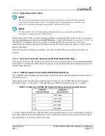
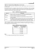
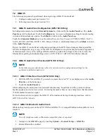
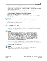
10. Remove power from GTN Xi #1 and apply power to GTN Xi #2. Acknowledge the prompts until
the
Instrument Panel Self-Test
page displays. Refer to Section 6.1.1. Select GPS2 by pressing the
NAV
key on the SN3308.
11. Repeat steps 5 through 9 with GTN Xi #2.
7.3.3.2.3 Dual GTN Xi Units/Dual SN3308s
1. Remove power from GTN Xi #2.
2. Cycle power to GTN Xi #1 and acknowledge the prompts until on the
Instrument Panel Self- Test
page (refer to Section 6.1.1). Select GPS1 as the navigation source by pressing the
NAV
key on the
SN3308 #1. Verify that “GPS1” displays on the SN3308.
3. Ensure that the SN3308 receives valid heading. The Vertical Deviation Indication will not display
unless the SN3308 receives valid heading.
4. While GTN Xi #1 displays the
Instrument Panel Self-Test
page, verify that the SN3308 displays
the following data from GPS1:
Course Deviation: Half-scale left deviation, TO indication, flag pulled
Vertical Deviation: Half-scale up deviation, flag pulled
Active Waypoint: GARMN
5. On GTN Xi #1, verify that an OBS value displays and is not dashed out.
6. Acknowledge the self-test on GTN Xi #1 by touching the
Continue
key.
7. Select
VLOC
on GTN Xi #1 and verify that the SN3308 displays “NAV 1” or “NAV 2” depending
on which navigation source the GTN Xi is.
8. Using a VOR test set, verify that the CDI deviation on the SN3308 displays correctly.
9. Remove power from GTN Xi #1 and apply power to GTN Xi #2. Acknowledge the prompts until
the
Instrument Panel Self-Test
page displays (refer to Section 6.1.1).
10. Select GPS2 by pressing the
NAV
key on the SN3308.
11. Repeat steps 4 through 8 with GTN Xi #2.
Perform the same procedure for the second SN3308. Ensure that SN3308 #2 receives valid heading by
ensuring the vertical deviation indication displays.
Содержание GTN Xi Series
Страница 42: ......
Страница 92: ...190 01007 C1 GTN Xi Part 23 AML STC Maintenance Manual Rev 1 Page 6 17 Figure 6 9 Fan Wiring Replacement...
Страница 163: ......

