background image

If your device has Wi

Fi technology, you should access the 

Garmin Quickdraw Community using the ActiveCaptain app 

(

Connecting to the Garmin Quickdraw Community with 

ActiveCaptain

, page 11

).

1

Insert the memory card into your computer.

2

Access the Garmin Quickdraw Community (

Connecting to the 

Garmin Quickdraw Community with Garmin Connect

page 11

).

3

Select 

Search for Contours

.

4

Use the map and search features to locate an area to 

download.
The red dots represent Garmin Quickdraw Contours maps 

that have been shared for that region.

5

Select 

Select an Area to Download

.

6

Drag the edges of the box to select the area to download.

7

Select 

Start Download

.

8

Save the file to your memory card.

TIP: 

If you cannot find the file, look in the "Downloads" folder. 

The browser may have saved the file there.

9

Remove the memory card from your computer.

10

Insert the memory card into the card reader. 
The chartplotter automatically recognizes the contours maps. 

The chartplotter may take a few minutes to load the maps.

Garmin Quickdraw Contours Settings

From a chart, select 

Menu

 > 

Quickdraw Contours

 > 

Settings

.

Display

: Displays Garmin Quickdraw Contours. The User 

Contours option shows your own Garmin Quickdraw 

Contours maps. The Community Contours option shows the 

maps you have downloaded from the Garmin Quickdraw 

Community.

Recording Offset

: Sets the distance between the sonar depth 

and the contour recording depth. If the water level has 

changed since your last recording, adjust this setting so the 

recording depth is the same for both recordings.
For example, if the last time you recorded had a sonar depth 

of 3.1 m (10.5 ft.), and today's sonar depth is 3.6 m (12 ft.), 

enter -0.5 m (-1.5 ft.) for the a Recording Offset value.

User Display Offset

: Sets differences in contour depths and 

depth labels on your own contours maps to compensate for 

changes in the water level of a body of water, or for depth 

errors in recorded maps.

Comm. Display Offset

: Sets differences in contour depths and 

depth labels on the community contours maps to compensate 

for changes in the water level of a body of water, or for depth 

errors in recorded maps.

Survey Coloring

: Sets the color of the Garmin Quickdraw 

Contours display. When this setting is turned on, the colors 

indicate the quality of the recording. When this setting is 

turned off, the contour areas use standard map colors.
Green indicates good depth and GPS position, and a speed 

under 16 km/h (10 mph). Yellow indicates good depth and 

GPS position, and a speed between 16 and 32 km/h (10 and 

20 mph). Red indicates poor depth or GPS position, and a 

speed above 32 km/h (20 mph).

Depth Shading

: Specifies the minimum and maximum depths of 

a depth range and a color for that depth range.
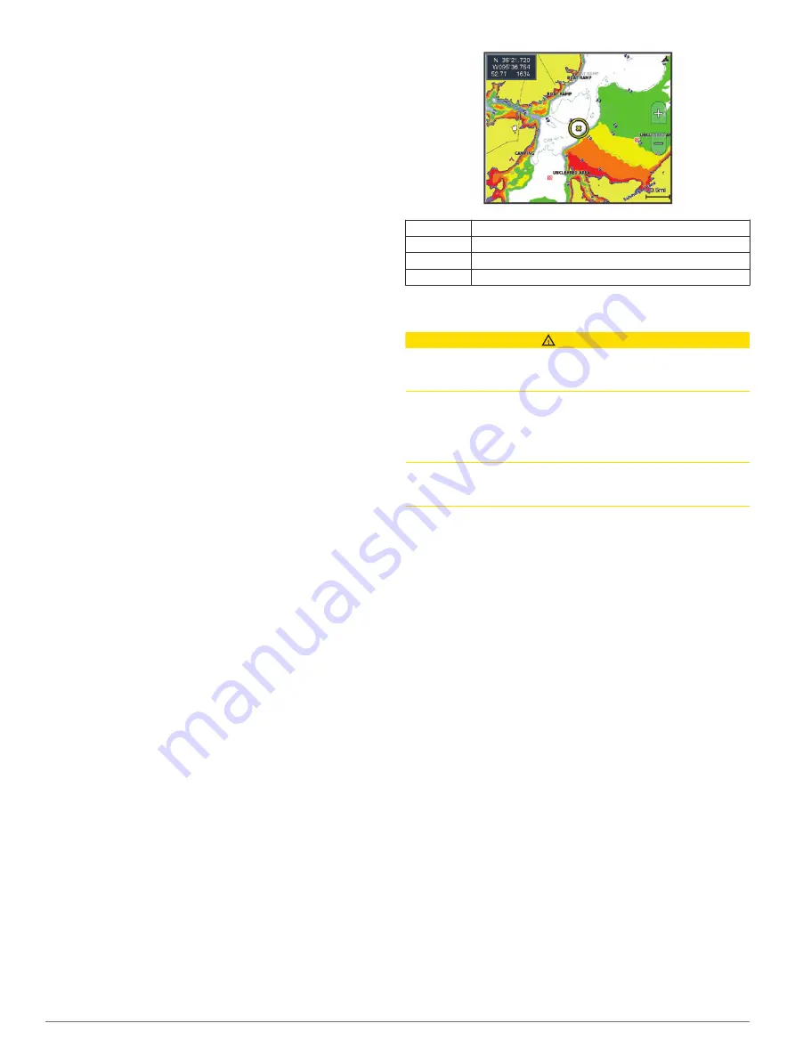
Depth Range Shading

You can set color ranges on your map to show the water depths 

where your target fish are currently biting. You can set deeper 

ranges to monitor how quickly the bottom depth changes within 

a specific depth range. You can create up to ten depth ranges. 

For inland fishing, a maximum of five depth ranges can help 

reduce map clutter.

Red

From 0 to 1.5 m (from 0 to 5 ft.)

Orange

From 1.5 to 3 m (from 5 to 10 ft.)

Yellow

From 3 to 4.5 m (from 10 to 15 ft.)

Green

From 4.5 to 7.6 m (from 15 to 25 ft.)

Navigation with a Chartplotter

 CAUTION

If your vessel has an autopilot system, a dedicated autopilot 

control display must be installed at each steering helm in order 

to disable the autopilot system.
The Auto Guidance feature is based on electronic chart 

information. That data does not ensure obstacle and bottom 

clearance. Carefully compare the course to all visual sightings, 

and avoid any land, shallow water, or other obstacles that may 

be in your path.
When using Go To, a direct course and a corrected course may 

pass over land or shallow water. Use visual sightings, and steer 

to avoid land, shallow water, and other dangerous objects.

NOTE: 

Some chart views are available with premium charts, in 

some areas.
To navigate, you must choose a destination, set a course or 

create a route, and follow the course or route. You can follow 

the course or the route on the Navigation chart, Fishing chart, 

Perspective 3D chart view, or Mariner’s Eye 3D chart view.
You can set and follow a course to a destination using one of 

three methods: Go To, Route To, or Auto Guidance.

Go To

: Takes you directly to the destination. This is the 

standard option for navigating to a destination. The 

chartplotter creates a straight-line course or navigation line to 

the destination. The path may run over land and other 

obstacles.

Route To

: Creates a route from your location to a destination, 

allowing you to add turns along the way. This option provides 

a straight-line course to the destination, but allows you to add 

turns into the route to avoid land and other obstacles.

Auto Guidance

: Uses the specified information about your 

vessel and chart data to determine the best path to your 

destination. This option is available only when using a 

compatible premium chart in a compatible chartplotter. It 

provides a turn-by-turn navigation path to the destination, 

avoiding land and other obstacles (

Auto Guidance

page 15

).

When you are using a compatible Garmin autopilot 

connected to the chartplotter using NMEA 2000

®

, the 

autopilot follows the Auto Guidance route.

NOTE: 

Auto Guidance is available with premium charts, in 

some areas.

12

Navigation with a Chartplotter

Содержание GPSMAP 8500

Страница 1: ...GPSMAP 8000 8500SERIES Owner sManual...

Страница 2: ...min Connect Garmin Express Garmin Helm Garmin LakeV Garmin Nautix Garmin Quickdraw GCV GMR GRID GXM HomePort MotionScope OneChart Panoptix Shadow Drive and SmartMode are trademarks of Garmin Ltd or it...

Страница 3: ...ting a Target for an AIS Vessel 8 Viewing a List of AIS and MARPA Threats 8 Setting the Safe Zone Collision Alarm 8 AIS Distress Signals 8 Navigating to a Distress Signal Transmission 8 AIS Distress S...

Страница 4: ...n of Sonar Signals 20 Changing the Sonar View 20 Traditional Sonar View 20 Split Frequency Sonar View 20 Split Zoom Sonar View 20 Garmin ClearV Sonar View 20 SideV Sonar View 20 SideV Scanning Technol...

Страница 5: ...to a Vessel in Distress 34 Man Overboard Distress Calls Initiated from a VHF Radio 34 Man Overboard and SOS Distress Calls Initiated from the Chartplotter 34 Position Tracking 35 Viewing a Position R...

Страница 6: ...ion Chart 43 Weather Overlay Settings on the Fishing Chart 43 Viewing Weather Subscription Information 43 Viewing Video 43 Selecting a Video Source 43 Alternating Among Multiple Video Sources 43 Netwo...

Страница 7: ...Chartplotter 52 Pairing the GRID Device with the Chartplotter from the Chartplotter 52 Pairing the GRID Device with the Chartplotter from the GRID Device 52 Rotating the GRID Joystick 52 Cleaning the...

Страница 8: ......

Страница 9: ...menu Turns on and off the radar echo trails Acquires a radar target and begins tracking it Shows and sets the VRM EBL line Opens the menu for the page or function Opens the Weather menu for the page...

Страница 10: ...reen you can return to the home screen by selecting Home When multiple displays are installed on the Garmin Marine Network you can group them together into a station A station enables the displays to...

Страница 11: ...n navigating select Navigation and select an option To turn on other data bars like the media controls select Top Bar or Bottom Bar and select the necessary options 3 Select Done Resetting the Station...

Страница 12: ...er Garmin Quickdraw contours you have downloaded or created Yes Push smart notifications Yes Yes Automatically transfer user data such as waypoints and routes Yes Begin navigating to a specific waypoi...

Страница 13: ...2 Enter a new channel You do not need to change the wireless channel of devices connected to this network Changing the Wi Fi Host You can change which chartplotter is serving as the Wi Fi host The can...

Страница 14: ...rect course and a corrected course may pass over land or shallow water Use visual sightings and steer to avoid land shallow water and other dangerous objects NOTE The Fishing chart is available with p...

Страница 15: ...the land Select Photo Map to show photos on both the water and the land at a specified opacity Use the slider bar to adjust the photo opacity The higher you set the percentage the more the satellite...

Страница 16: ...to include in the list Setting the Safe Zone Collision Alarm Before you can set a collision alarm you must have a compatible chartplotter connected to an AIS device or radar The safe zone collision a...

Страница 17: ...yer Depth Layer Settings page 9 Depth Layer Settings From a chart select Menu Layers Chart Depth Depth Shading Specifies an upper and lower depth to shade between Shallow Shading Sets the shades from...

Страница 18: ...enu Layers Radar From a radar screen select Menu Radar To Standby Stops radar transmission Gain Adjusts the gain Adjusting Gain on the Radar Screen Automatically page 30 Sea Clutter Adjusts the sea cl...

Страница 19: ...been shared for that area 3 Select Select Download Region 4 Drag the box to select the area to download 5 Drag the corners to change the download area 6 Select Download Area The next time you connect...

Страница 20: ...eed above 32 km h 20 mph Depth Shading Specifies the minimum and maximum depths of a depth range and a color for that depth range Depth Range Shading You can set color ranges on your map to show the w...

Страница 21: ...from the Navigation or Fishing chart select an option Select Menu Stop Navigation When navigating with Auto Guidance select Menu Navigation Options Stop Navigation Waypoints Waypoints are locations yo...

Страница 22: ...cation of your vessel The last turn you add should be the first turn you make starting from your present location It should be the turn closest to your vessel 6 If necessary select Menu 7 Select Done...

Страница 23: ...Destinations page 13 2 Select Navigate To Auto Guidance 3 Review the path indicated by the magenta line 4 Select Start Navigation 5 Follow the magenta line steering to avoid land shallow water and ot...

Страница 24: ...ance setting to Near or Nearest As a result the chartplotter may not reposition the Auto Guidance line unless the destination selected requires navigation through a narrow waterway 8 Select an option...

Страница 25: ...the map You can also convert saved tracks and routes into boundary lines You can create a boundary area using waypoints by creating a route from the waypoints and converting the route into a boundary...

Страница 26: ...art Line 2 Select an option To mark the port and starboard starting line marks as you sail past them select Ping Marks To mark the port and starboard starting line marks by entering their coordinates...

Страница 27: ...advanced autopilot configuration see the installation instructions included with your autopilot 1 From the autopilot screen select Menu Autopilot Setup Wind Hold Type 2 Select Apparent or True Engagi...

Страница 28: ...the split frequency view you can separately adjust the gain for each frequency If you do not see an arrangement of sonar views to suit your needs you can create a custom combination screen Creating a...

Страница 29: ...l around the boat in real time You can also watch your bait underwater and bait schools in front of or below your boat The LiveV sonar views provide you a view of the live movement either in front of...

Страница 30: ...equency transducer select Dual Frequency 200 50 kHz If you have another type of transducer select it from the list Calibrating the Compass Before you can calibrate the compass the transducer must be i...

Страница 31: ...as of interest on the sonar screen by adjusting the color gain for traditional transducers or the contrast for Garmin ClearV and SideV ClearV transducers This setting works best after you have adjuste...

Страница 32: ...to adjust the range automatically select Auto To increase or decrease the range manually select Up or Down TIP From the sonar screen you can select or to manually adjust the range TIP When viewing mu...

Страница 33: ...allation Transmit Rate Sets the length of time between sonar pings Increasing the transmit rate increases the scroll speed but it may also increase self interference Reducing the transmit rate increas...

Страница 34: ...difficult to recognize actual returns Depth Range Adjusts the range of the depth scale Allowing the device to adjust the range automatically keeps the bottom within the lower portion of the sonar scr...

Страница 35: ...V LiveV Forward and RealV 3D Forward sonar views Beam Width Sets the width of the down view Panoptix transducer beam Narrow beam widths allow you to see deeper and farther Wider beam widths allow you...

Страница 36: ...he radar enters standby mode after it warms up This gives you an opportunity to verify the area around the radar is clear before beginning radar transmission 1 With the chartplotter off connect your r...

Страница 37: ...the location of the outer guard zone corner 3 Select Corner 2 4 Touch the location of the inner guard zone corner to define the width of the guard zone 5 Select Done Disabling a Guard Zone You can dis...

Страница 38: ...M EBL 3 Select Stop Pointing Measuring the Range and Bearing to a Target Object Before you can adjust the VRM and the EBL you must show them on the Radar screen Showing the VRM and the EBL page 30 1 F...

Страница 39: ...on the Radar Screen Manually You can adjust the appearance of clutter caused by choppy sea conditions The sea clutter setting affects the appearance of nearby clutter and targets more than it affects...

Страница 40: ...n which the radar does not transmit signals Enabling and Adjusting a Radar No Transmit Zone page 28 Front of Boat Offset The front of boat offset compensates for the physical location of the radar sca...

Страница 41: ...topilot activates Shadow Drive mode When you release the helm and manually maintain a specific heading for a few seconds the autopilot resumes a heading hold at the new heading Adjusting the Heading w...

Страница 42: ...up and send individual routine call details to your Garmin VHF radio When you initiate a man overboard distress call from your radio the chartplotter shows the man overboard screen and prompts you to...

Страница 43: ...four hours old appear for all tracked vessels Individual Routine Calls When you connect the chartplotter to a Garmin VHF radio you can use the chartplotter interface to set up an individual routine c...

Страница 44: ...ms 1 From the engine gauges screen select Menu Installation Status Alarms Custom 2 Select one or more engine gauge alarms to turn on or off Setting the Fuel Alarm Before you can set a fuel level alarm...

Страница 45: ...sources of power such as solar alternator converter and wind generator are listed along the left side The items along the right side of the screen are devices that use the batteries and other power s...

Страница 46: ...ources 2 Select a source Playing Music Browsing for Music 1 From the media screen select Browse or Menu Browse 2 Select Select or select an option Enabling Alphabetical Search You can enable the alpha...

Страница 47: ...scan for DAB stations When the re scan is complete the system starts playing the first station in the ensemble you were listening to when you started the re scan Changing DAB Stations 1 Select the DA...

Страница 48: ...usXM Radio Before you can clear all locked channels the parental controls must be unlocked 1 From the media screen select Browse Parental Clear All Locked 2 Enter your passcode Setting the Device Name...

Страница 49: ...l pass as received from the weather data provider Weather Warnings and Weather Bulletins When a marine weather warning weather watch weather advisory weather bulletin or other weather statement is iss...

Страница 50: ...shading indicates the surface temperature of the water as shown in the legend in the corner of the display Forecasting Fish Locations You can show areas that contain optimal weather conditions for sp...

Страница 51: ...the amount of time each video appears 3 Select Source and select the video sources to add to the alternating sequence Networked Video Devices NOTICE A Garmin Power over Ethernet PoE Isolation Coupler...

Страница 52: ...gestures allows video control without displaying the video controls 1 From a video screen touch the screen 2 Select an option To zoom in and out with the camera use pinch and zoom gestures To pan or...

Страница 53: ...Photo Takes a still photograph Sleep Puts the VIRB action camera into a low power mode to conserve battery power VIRB Action Camera Video Setup Settings Select A V Gauges Controls VIRB Menu Video Set...

Страница 54: ...u can view the software version the basemap version all supplemental map information if applicable the software version for an optional Garmin radar if applicable and the unit ID number You may need t...

Страница 55: ...n obstacles select Settings Preferences Navigation Auto Guidance Shoreline Distance Far If the turns in the Auto Guidance line are too wide select Settings Preferences Navigation Auto Guidance Shoreli...

Страница 56: ...rom an applicable sonar view select Menu Sonar Setup Alarms You can also open the sonar alarms by selecting Settings Alarms Sonar Shallow Water Sets an alarm to sound when the depth is less than the s...

Страница 57: ...e measured in step 1 from the water temperature measured in step 2 This is the temperature offset Enter this value in step 5 as a positive number if the sensor connected to the chartplotter measures t...

Страница 58: ...nly boundary files with an adm extension are supported 1 Insert a memory card into a card slot 2 Select Info User Data Data Transfer 3 If necessary select the memory card to copy data to 4 Select an o...

Страница 59: ...o www garmin com support software marine html select See All Devices in this Bundle and compare the installed software version to the software version listed for your product If the software on your d...

Страница 60: ...he memory card 3 Copy a bmp file from the card and paste it to any location on the computer Troubleshooting My device will not acquire GPS signals If the device is not acquiring satellite signals ther...

Страница 61: ...rent draw at 12 Vdc 1 3 A Max current draw at 12 Vdc 2 8 A Compass safe distance 310 mm 12 2 in Twelve inch models Dimensions W H D 333 247 97 mm 137 64 923 32 313 36 in Display size W H 245 184 mm 92...

Страница 62: ...D Bearing origin to destination GPBWC BWC Bearing and distance to waypoint GPGGA GGA Global positioning system fix data GPGLL GLL Geographic position latitude and longitude GPGSA GSA GNSS DOP and acti...

Страница 63: ...inations navigation chart 13 selecting 13 device cleaning 52 registration 51 digital selective calling 34 35 channels 35 contacts 34 individual routine call 35 turning on 34 49 digital switching 51 di...

Страница 64: ...adow Drive enabling 33 sharing data 50 shoreline distance 16 47 SideV 20 SiriusXM 38 40 Satellite Radio 39 SiriusXM Satellite Radio 39 40 SmartMode layout linking to boundary 17 software updates 40 51...

Страница 65: ...ription 40 43 surface pressure 42 visibility 42 water temperature 42 wave information 42 winds 42 Wi Fi 4 Wi Fi technology 5 wind rose 9 wind angle graph 37 wind gauges 36 37 wind hold 19 adjusting 19...

Страница 66: ...support garmin com October 2017 190 01557 00_0L...

Отзывы: