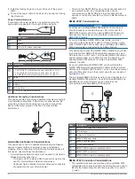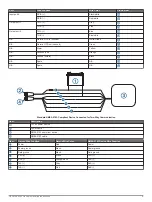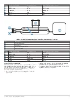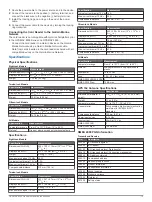
Item Description
10–35 Vdc power source
Power cable
Horn
Lamp
NMEA 0183 cable
Relay (100 mA coil current)
Toggle switches to enable and disable lamp or horn alerts
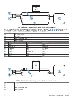
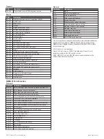
Item
Wire Color
Wire Function
Red
Power
Black
Ground
Yellow
Alarm
Video Input and Output Considerations
This device allows video input from composite, component, and
digital video sources, depending on the model, and video output
to a monitor. When connecting video input and output sources,
observe these considerations.
• The eight- and twelve-inch models have two composite-video
ports labeled CVBS 1 IN, and CVBS 2 IN. The fifteen-inch
models have four composite-video ports labeled CVBS 1 IN,
CVBS 2 IN, CVBS 3 IN, and CVBS 4 IN.
• The fifteen-inch models have one component-video port
labeled COMPONENT IN (480i/576i).
◦ The composite- and component-video ports use BNC
connectors. You can use a BNC to RCA adapter to
connect a composite-video source with RCA connectors to
these ports.
◦ The video from sources connected to these ports is
available only for display on the device or additional
monitor connected to the device. Composite or component
video is not shared across the Garmin Marine Network or
NMEA 2000 network.
• The fifteen-inch models have one video port labeled DVI-I
VIDEO IN that accepts video from digital or analog sources
using a DVI-D or DVI-I cable.
◦ If needed, you can use an HDMI to DVI-D converter to
connect an HDMI-compatible source to this device.
◦ If needed, you can use a VGA to DVI-I adapter to connect
a VGA source to this port.
• You can connect a display to the DVI-I VIDEO OUT port to
view a mirror image of the screen on a computer monitor or
HD TV using a DVI-D or DVI-I cable.
◦ If needed, you can use a DVI-D to HDMI adapter to
connect to an HD TV or other HDMI-compatible display.
◦ If needed, you can use a DVI-I to VGA adapter to connect
to a computer monitor or other VGA-compatible display.
• Although it is recommended to use DVI cables sold by
Garmin, high-quality third-party DVI cables may be used. You
should test the DVI cable by connecting the devices before
routing the cable.
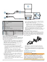
Video Connector Gasket Considerations
Rubber gaskets are included for all DVI and VGA connections
on the device. These gaskets must be installed between each
DVI or VGA port and cable connector to avoid damage to the
connectors. When making DVI or VGA connections, observe
these considerations.
• Blue gaskets are included for use with DVI connections.
• Gray gaskets are included for use with VGA connections.
• When installing the gasket between a VGA cable connector
and port, the arrow on the side of the seal must point toward
the device.
Card Reader Connections
Connecting to Power
WARNING
When connecting the power cable, do not remove the in-line
fuse holder. To prevent the possibility of injury or product
damage caused by fire or overheating, the appropriate fuse
must be in place as indicated in the product specifications. In
addition, connecting the power cable without the appropriate
fuse in place will void the product warranty.
12
GPSMAP 8000 Series Installation Instructions

