


GTS 8XX/GPA 65 Installation Manual
Page 3-17
190-00587-00
Revision 4TP
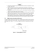
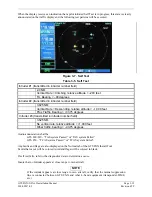
3.5.6 Antenna
Verification
The first step in antenna verification is to verify auto-calibration operates without indicating a fault.
1.
With the GTS 8XX powered up and “Standby” indicated on the CDTI cycle the GTS 8XX to
“Operate”. Each time the GTS 8XX transitions between these modes a self test of the antenna
circuit is initialized. If the antenna connection is not correct the CDTI will display “Failure”
indicating it will be necessary to recheck the antenna coaxial connections. If the CDTI
displays “Operate” without indicating a fault, proceed to the next step of antenna verification.
Using a ramp tester, such as a TIC TR220 or equivalent, make the following set up and measurements to
assure the antenna is properly connected and the GTS 8XX is operational.
2.
Position the test set directional antenna with a clear line of sight to the GTS8XX antenna.
3.
Ensure that the transmitter or receiver (RX/TX) that you are testing is significantly closer to the
ramp tester than another operating RX/TX, or erroneous and inaccurate results may occur. All
four quadrants (forward, starboard, aft, and port) will be similarly tested to verify bearing of
simulated intruder supplied via the ramp tester are correctly displayed on the CDTI.
4.
Using the ramp tester, select the proper antenna gain and distance to aircraft.
5.
Position ramp test set at 0 degrees.
6.
Turn the test set on.
7.
Connect the directional antenna to the ramp test set.
8.
Set the multifunction test set to perform “TCAS” testing. Configure the GTS 8XX to the
normal operating mode.
9.
Program a static intruder per the following scenario:
NOTE
See ramp test set operators manual to set the following parameters
Intruder Start Distance
Intruder Start Altitude
Vertical Speed
Velocity
2
NM
50,000
0
fpm.
0
Kts
10.
Set the intruder type as ATCRBS.
11.
Verify a target is annunciated on the GTS 8XX TAS/TCAS display at the correct bearing of
approximately 0 degree azimuth at 2 NM and co-altitude (read as 00 above a filled diamond
indicating proximate traffic).
12.
Toggle intruder traffic to standby or off.
13.
Reposition ramp test set and directional antenna to a starboard position of 90 degrees.


