


GTS 8XX/GPA 65 Installation Manual
Page iii
190-00587-00
Revision 4TP
TABLE OF CONTENTS
PARAGRAPH
PAGE
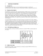
1 GENERAL
DESCRIPTION..............................................................................................................1-1
1.1 Introduction........................................................................................................................................1-1
1.2 Equipment
Description ......................................................................................................................1-1
1.3 Interface Summary.............................................................................................................................1-1
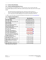
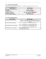
1.4 Technical
Specifications ....................................................................................................................1-2
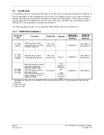
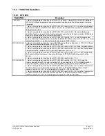
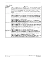
1.5 Certification .......................................................................................................................................1-4
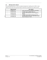
1.6 Reference
Documents ........................................................................................................................1-8
1.7 Limited
Warranty...............................................................................................................................1-9
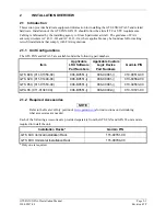
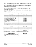
2 INSTALLATION
OVERVIEW ........................................................................................................2-1
2.1 Introduction........................................................................................................................................2-1
2.2 Installation
Considerations ................................................................................................................2-3
2.3 Electrical Bonding .............................................................................................................................2-5
2.4 Cabling
and
Wiring............................................................................................................................2-5
2.5 Cooling
Requirements .....................................................................................................................2-15
2.6 Mounting
Requirements ..................................................................................................................2-16
3 INSTALLATION
PROCEDURE......................................................................................................3-1
3.1 Unpacking
Unit..................................................................................................................................3-1
3.2 Wiring Harness Installation ...............................................................................................................3-1
3.3 QMA Connector Insertion and Removal ...........................................................................................3-3
3.4 Backshell, Pigtail Circular Connector, and Configuration Module Assemblies................................3-5
3.5 Unit
Installation .................................................................................................................................3-5
3.6 GA 58 Antenna Installation .............................................................................................................3-19
3.7 GPA 65 PA/LNA Installation ..........................................................................................................3-20
3.8 Continued
Airworthiness .................................................................................................................3-20
4 SYSTEM
INTERCONNECTS..........................................................................................................4-1
4.1 GTS 8XX Pin Function List ..............................................................................................................4-1
4.2 GPA 65 Pin Function List..................................................................................................................4-6
4.3 Power .................................................................................................................................................4-7
4.4 Serial
Data .........................................................................................................................................4-9
4.5 Configuration ...................................................................................................................................4-12
4.6 Analog/Discrete ...............................................................................................................................4-12
4.7 Mutual Suppression Bus ..................................................................................................................4-14
APPENDIX A: OUTLINE & INSTALLATION DRAWINGS .............................................................. A-1
APPENDIX B: INTERCONNECT EXAMPLE...................................................................................... B-1