Page 2-14
GTS 8XX/GPA 65 Installation Manual
Revision 4TP
190-00587-00
2.4.1.4 Coaxial
Cable
Assembly Instructions
The following assembly instructions apply to coaxial cables assemblies using QMA connectors specified
in Table 2-2 for use with RG-400 or RG-142 cable types:
1.
Slide the heat shrink sleeve and crimp ferrule onto the cable.
2.
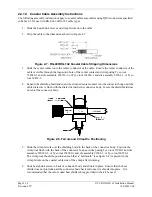
Strip the cable to the dimensions shown in Figure 2-7.
Figure 2-7. RG-400/RG-142 Coaxial Cable Stripping Dimensions
3.
Slide the center contact onto the center conductor of the cable. Ensure the center conductor of the
cable is visible through the inspection hole of the center contact and crimp using Tyco tool
354940-1 and die assembly 220189-3, or Tyco tool 354940-1 and die assembly 91901-1, or Tyco
tool 69478-1.
4.
Expand the shielding braid and insert the crimped center contact into the connector body until the
cable dielectric is flush with the dielectric inside the connector body. Insure the shield braid does
not enter the connector body.
Figure 2-8. Ferrule and Crimp Die Positioning
5.
Slide the crimp ferrule over the shielding braid to the back of the connector body. Position the
crimp tool flush with the back of the connector body and crimp using Tyco tool 35940-1 and die
assembly 220189-3, or Tyco tool 354940-1 and die assembly 91901-1, or Tyco tool 69478-1.
The crimp tool should be positioned such that a “bellmouth” (see figure 2-8) is present in the
crimp ferrule on the coaxial cable side of the crimp after crimping.
6.
Slide heat shrink sleeve to back of connector body and shrink in place. Ensure that the heat
shrink does not protrude past the connector body back end once it is shrunk into place. It is
recommended that the color-coded heat shrink tubing provided in the kit be used.


