


26
III. Cabling the Fixture
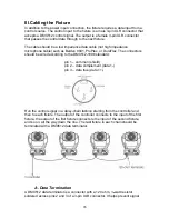
In addition to the power input connection, the fixture requires a data input from a
control source. The control input to the fixture is a male 3-pin XLR connector that
accepts a DMX512 control signal. The output is a female 3-pin XLR connector
that passes the control data through to the next fixture.
The cable should be a low impedance data cable (not high impedance
microphone cable) such as Belden 9841, ProPlex, or DuraFlex. The connectors
should be wired according to the DMX512-1998 standard:
pin 1 – common (shield)
pin 2 – data complement (data 1-)
pin 3 – data true (data 1+).
Run the control signal in a daisy-chain fashion starting from the controller and
then to each fixture. The output of the controller connects to the input of the first
fixture, the output of the first fixture connects to the input of the second fixture,
and so on, all the way down the line. The last fixture in each chain should be
terminated with a DMX512 data terminator.
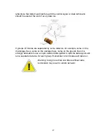
A. Data Termination
A DMX512 data terminator is a connector with a 120 ohm, ¼-watt resistor
soldered across pins 2 and 3 of a 3-pin XLR connector. It helps prevent signal
Содержание GKH 575
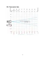
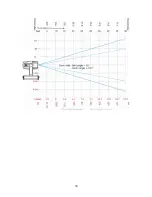
Страница 37: ...37 VIII Photometric Data...
Страница 38: ...38...


