i)
Settle the weeder into the crop rows with all tractor wheels and the weeder well into the crop. You
should see the self levelling system adjust the steer discs in order to set the toolbar height. Put the 3
point linkage into the float position (never use pressure down). Adjust the top link so that the weeder
is level and the camera stem is vertical. The self levelling system monitors the position of the outside
most row unit parallel linkages to ensure the toolbar height stays a constant height above the soil
around the plants irrespective of wheeling depth or bed height. If the toolbar appears to be always
higher on one side than on the other consult your service agent.
3)
Press “Setup” and check the basic settings.
i)
Crop size
- set to height of thickest part of foliage.
ii)
Configuration
– Check that the intended file is highlighted in white.
iii)
Plant spacing
- measure distance of 5 plant spaces and divide by 5 in at least 4 places and use the
average or set to a slightly smaller setting if it is found some plants do not get selected with a cross
while working.
iv)
Clearance
– start with the setting on Normal. This feature allows the non cultivated plant zone size to
be adjusted.
v)
Crop Colour
– set to suit the crop. If crop is a mix of red and green it may be necessary to work in
infra red mode (ask your service agent).
vi)
Camera >
Row quantity and width
- It is the operator’s responsibility to measure the crop and adjust
the implement and computer settings to match the crop
vii)
Camera >
Height
– settle the weeder onto the crop with all tractor wheels and the weeder well into
the crop so that everything is level. Measure the height from soil to camera lens. Check that the
height matches the setting in the configuration file. If not then adjust the camera on its bracket to the
setting shown on the console
viii)
Camera >
Look ahead
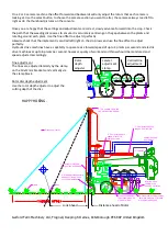
–check that the machine is level (camera stem vertical), if not adjust the top
link of the tractor 3 point linkage until it is. Ensure that every time you enter the crop, the implement
always settles to the same position by using the 3 point linkage in the
float position
(never impose
pressure down from the tractor via the tractor 3 point linkage!!). With the “manual” button pressed,
measure the distance along the soil from the point directly vertically below the camera lens to the
cross hairs on the camera image. This is the
look ahead
distance.
ix)
Camera > A
head of rotors
– the distance back from the point below the camera lens to the rotational
centre of the rotor discs. If the discs are ahead of the camera lens filter then the distance is entered
as a negative.
x)
Camera >
Disc Size
see section 1. iii above
4)
Press the “Manual” button so that the grid lines appear. Go to setup>Advanced menu and set camera skew to
zero, then return to the working screen. If the grid, for each camera, does not exactly match the crop rows,
check the
camera lateral adjustment
, if necessary move the camera sideways until the grid is centred. If the
overall size of the grid looks wrong go to config editor and check the Camera >
focal length setting
. 2008
cameras should have a 4mm lens with focal length of 0.0185mm (0.7283”) and 2009 have a 2.9mm lens with
focal length of 0.0133mm (0.5253”).
5)
Check that the in work sensor is set correctly and switches the grid on and off as the implement is lowered
and raised. Check that the odometer wheel is reliably in contact with the soil and soil flow is not impeded by
tines close to the wheel.
6)
Check hydraulic oil supply pressure before commencing work and during working at full speed to be sure the
oil supply is sufficient. Oil pressure should be stable and not fall below 150bar (2100psi). The return line
pressure should be near to zero, please check it, if it is more than 20 bar refer to your service agent.
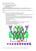
Fine offset-
the two central buttons facilitate adjustment of the offset. Each press of
the button will move the cutting position by 1cm.
Start with the fine offset indicator dead centre. Right/left adjustment moves the
whole implement in relation to the crop position on the camera, forward/rearward
adjustment advances or retards the rotation of the rotor disc as the implement advances forwards.
Содержание Robocrop Inrow Weeder
Страница 1: ...Operator Instructions...


