

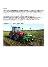


Robocrop InRow Weeder – Setup Guide
Setting up the Robocrop InRow Weeder consists of..
mechanical alignment of the weeding units
mechanical alignment of the cameras
configuration file settings
The inter relationship between all of these settings is critical
; if one is wrong the weeder will not work
accurately. The accuracy of taking measurements and setting the weeder will be reflected in the accuracy of
work.
It is the operator’s responsibility to measure the crop and adjust the implement and computer settings to match
the crop.
1)
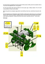
The implement must be set up physically to suit the crop you are working on.
i)
Set the disc steer wheel track width to suit the crop track width
ii)
Set the weeder row units to suit the row widths to be worked (Always take these measurements from
the crop in the field to be worked).
iii)
Ensure the rotor disc size fitted suits the crop to be worked and the setting shown on the setup
screen. The disc size should be equal to or smaller than the plant spacing to be worked. The physical
measurement across the wide part of the disc is approximately half the disc design size i.e 126mm
disc width = 25cm disc size.
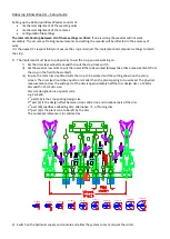
Disc size designation is a special code
e.g. 16-4W6
1
st
part (16) is the crop spacing design size
2
nd
part (4) is the design offset between crop centre line and rotational axis of the disc
3
rd
part (W) specifies a Weeding disc, alternative =T, a Thinning disc
4
th
part (6) is the plant zone to be left by the disc
The numerical reference is in centimetres.
10005
8619
8614
8619
8614
8619
8614
8619
8614
8677
8677
8677
8719
8093
8091
130
8093
8091
130
8570r2
8673
8672
8673
8672
8673
8672
8673
8672
8673
8672
8673
8672
8673
8672
8673
8672
10007
9735 SL 50W
7749
7744
180
7749
7744
180
7749
7744
180
16-4W6
8543
Leg
18-4W6
8543
Leg
21-4W6
Leg
8495
25-4W7
Leg
8495
29-4W7
Leg
8495
33-4W7
Leg
8495
29-6W10
8684
Leg
33-6W10
8684
Leg
38-6W10
8684
Leg
45-6W10
8684
Leg
16-4W6
18-4W6
21-4W6
25-4W7
29-4W7
33-4W7
29-6W10
33-6W10
38-6W10
45-6W10
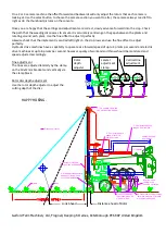
2)
Switch on the hydraulic supply and console and allow the system to test and park the rotors.
Содержание Robocrop Inrow Weeder
Страница 1: ...Operator Instructions...


