8
1
2
3
4
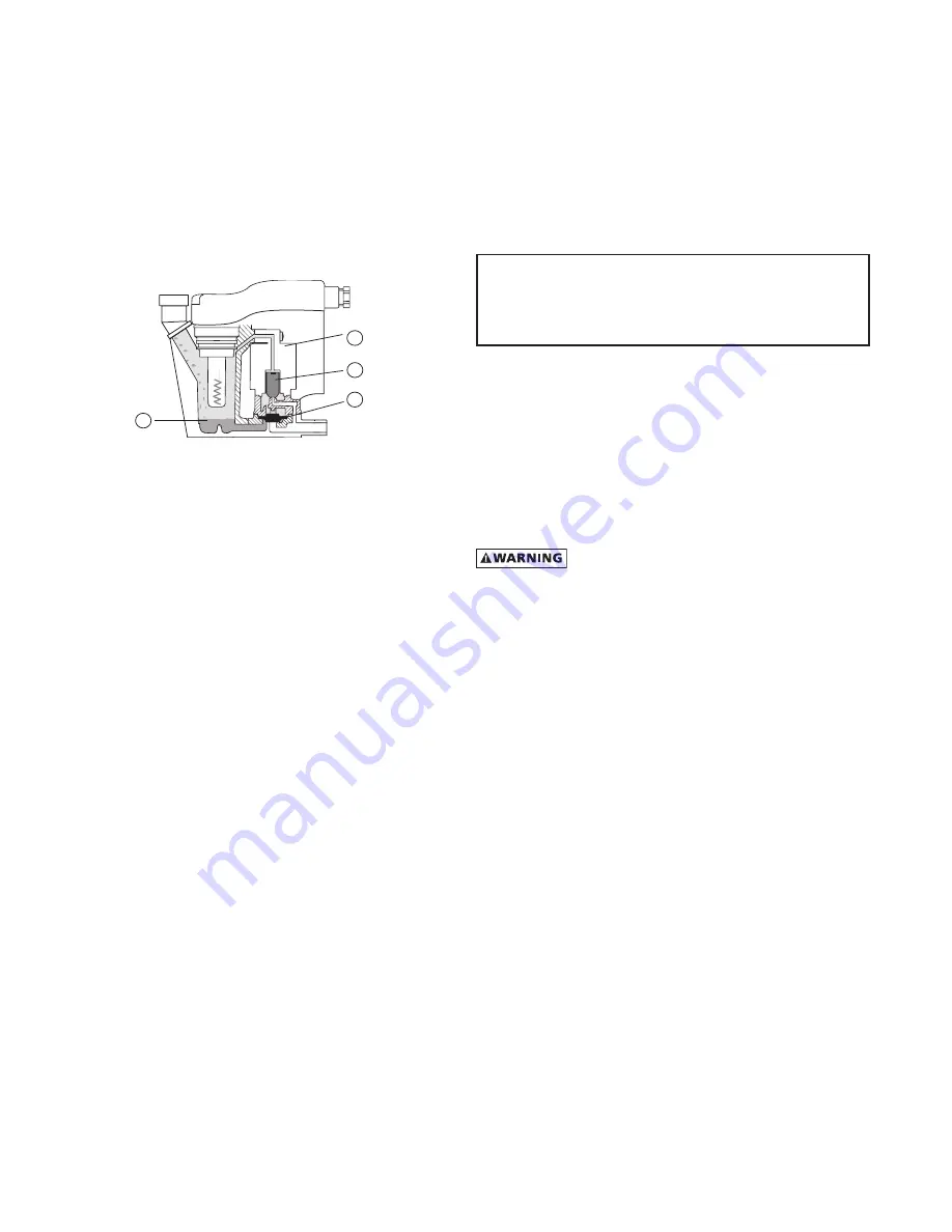
E. Condensate enters the reservoir
(1)
through the inlet
port. When the condensate level in the reservoir covers
the capacitance sensor, an electronic signal is sent to the
solid state countdown processor. The processor delays
the opening of the solenoid valve for a given period
of time. Once the time has elapsed, the solid state
processor transmits information to energize the coil in
the solenoid valve
(2)
. The magnetic force of the coil
causes the solenoid core
(3)
to move, closing the pilot air
supply line and opening the pilot air exhaust line. After
the pilot air above the diaphragm
(4)
is vented, pressure
in the reservoir opens the discharge port and forces
the condensate through the discharge port and outlet
piping.
2.8 Operating Instructions
– I-Controller Level 3
1. Check the following on a periodic basis:
a. Power-on light glows (green) indicating power to the
dryer
b. Compressor-on light glows (green) indicating the
refrigeration compressor is operating
c. VFTD is automatically scrolling every 3 seconds
through OPERATION mode readings and settings
d. Warning/Maintenance Alert light (yellow) is NOT
flashing
e. Alarm light (red) is NOT flashing
f. Condensate is draining
2. ALARM/ALERT Fault Condition Activation
(See wiring diagram for N/O contact location.)
Upon activation, text identifying the Fault will be
displayed on the VFTD. An Audible Alarm will sound, a
Flashing Panel light (Warning/Yellow or, Alarm/Red) and, a
Flashing Process Diagram LED (Green or Red) combine to
indicate the fault condition. Where applicable (see table
2 on page 20) a normally open (N/O) circuit will activate a
customer supplied remote alarm.
NOTE:
If yellow Alert light or, red Alarm light ARE flashing,
see fault condition identified in VFTD window. Reference the
condition in the Troubleshooting Guide on page 20.
3. REMOTE START/STOP Function
Software programming allows the dryer to be stopped
and started by a remotely controlled signal. Consult
factory for details.
4. DOWNLOADABLE MEMORY Function
Software programming allows the dryer to store the last
10 alarm related events. Output command delivers the
events complete with the date, time and, fault condition.
Consult factory for details.
5. RS-232 & RS-485 Communications Capable
Dedicated pin arrangement is used to monitor dryer
operation from a host computer. Consult factory for
details.
3.0 MAINTENANCE
3.1 Condenser coil
A. Air-cooled - clean off accumulated dust and dirt monthly
or as necessary in dirty environments.
B. Water-cooled - clean strainer monthly, more often if
required. Shut off water, remove small plug to relieve
pressure, then remove large plug to remove strainer.
Clean strainer and replace.
3.2 Moisture Separator/Oil Removal Filter
NOTE:
Prepackaged maintenance kits are available
that include all necessary filter and timed drain valve
components. Maintain maximum performance and
efficiency with Genuine Parts. See page 21 for ordering
information.
When to replace the Separator/Filters
Replace filter element when pressure drop across dryer is
excessive or annually.
Dryers have the option of one or two stages of filtration.
The directions for servicing either filter is identical.
When removing liquids at rated flow conditions, an
increase in pressure drop will occur as the separator/
filter elements become loaded with solid particles.
Procedure for Separator / Filter Element Replacement
THIS FILTER IS A PRESSURE CONTAINING DEVICE.
DEPRESSURIZE BEFORE SERVICING. If filter has not been
depressurized before disassembly, an audible alarm will sound
when the bowl begins to be removed from the head. If this
occurs, stop disassembly, isolate and completely depressurize
filter before proceeding.
1. Isolate dryer (close inlet and outlet valves if installed) or
shut off air supply.
2. Depressurize filter by slowly opening manual drain by-
pass valve.
3. Remove bowl
a. For models RNC100 through RNC150 - bayonet
mount - push bowl up, turn bowl 1/8th turn to your
left, and pull bowl straight down
b. For models RNC200 through RNC750 - threaded
bowls - unscrew bowl from head using hand, strap
wrench or C spanner.
4. Clean filter bowl
5. Replace moisture separator element.
a. Replacing complete Grade B element.
1) Pull off old element and discard
2) Make certain o-rings on male of replacement
element adaptor are in place and push element
into filter head.
NOTE:
Do not handle Oil Removal Filter elements by outside
foam cover. Handle by bottom end cap only.
Содержание RNC Series
Страница 22: ...22 NOTES...
Страница 23: ...23 NOTES...


