SB--7--622 Page 16
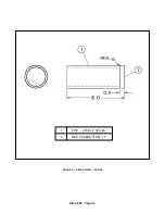
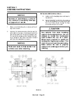
FIGURE 14
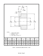
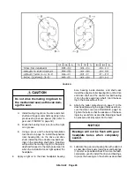
FIGURE 15
If backlash is above the specified lim-
it, the gears are not necessarily unus-
able. Excessive play could be caused
by worn bearings.
5.
If timing gears appear to be reusable, matchmark
timing gear toothmesh by making small punch
marks on the ends of meshing gear teeth with a
pin punch and hammer (see FIGURE 13, page
15). The impeller tip to valley (throat) and the case
to headplates should also be match marked to fa-
cilitate blower reassembly.
6.
Remove each timing hub (39) and the timing gear
(9) as a complete assembly with a gear puller.
(See FIGURE 14). Do not remove timing bolts
(38) or threaded taper pins (36), unless the gears
or hubs will be replaced.
If replacing the timing gears (9), re-
move the timing hub taper pins (36) by
placing washers or an oversized nut
over the extending threaded area of
the pin. Tighten a proper--sized nut
on the pin and it will eject.
7.
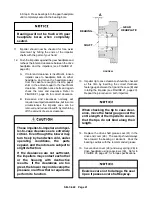
Remove the four socket head cap screws (30)
from the drive end bearing cover (29) and remove
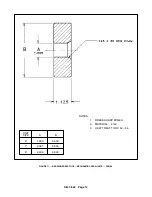
FIGURE 16
the cover. Drive shaft oil seal (31) should come
free when cover is removed.
8. Remove mounting foot (17) from the drive head-
plate (24) by removing the capscrews (16).
9. Remove the capscrews (21) which secure the
drive headplate (24) to the impeller case (22).
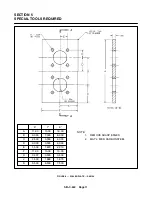
10. Using the fabricated puller plate shown on page
11, bolt to the drive headplate using the tapped
holes used to secure the drive cover.
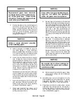
11. Install a gear puller to each shaft and attach the
puller arms to the fabricated plate. Turn each pull-
er only half a revolution at a time keeping the ad-
vance of the shafts as uniform as possible (see
Содержание LEGEND GAF P Series
Страница 19: ...SB 7 622 Page 12 1 PIPE STEEL 2 SCH 80 2 MED CARBON STEEL 1 2 FIGURE 9 GEAR DRIVER SK2150...
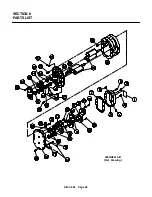
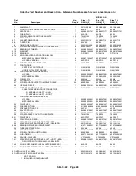
Страница 32: ...SB 7 622 Page 25 SECTION 8 PARTS LIST 300GAF810 B Ref Drawing...
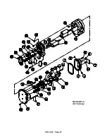
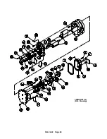
Страница 34: ...SB 7 622 Page 27 300GAG810 A Ref Drawing...
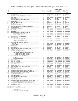
Страница 36: ...SB 7 622 Page 29 300GAH810 A Ref Drawing...
Страница 39: ......

