- 10 -
J
5
J
1
J
4
J
7
J
6
J
8
J
9
J
3
V
7
J
2
14
B
1
A
Q
1
X
1
A
1
Q
Q
2
15
7.2 Oil Mist Separator (Optional Extra Exhaust Side)
The oil mist separator which is mounted directly on the
exhaust fl ange of the vacuum pump is a 2-stage device:
Separation:
➞
liquid droplets in the condensate collector
➞
aerosol in the fi lter elements
The oil mist separators are available in 2 material variations
for the chemical and pharmaceutical industries:
➞
Stainless steel: 1.4541
➞
glass
The fi lter candles are made of tefl on or borosilicate glass
and hence are fully resistant to solvents and largely resist-
ant to acids.
Please note
: If the material being handled is subject to poly-
merisation or resin hardening it is not advisable to use this
type of oil mist separator as the fi lter elements would quickly
become blocked and would require frequent changing.
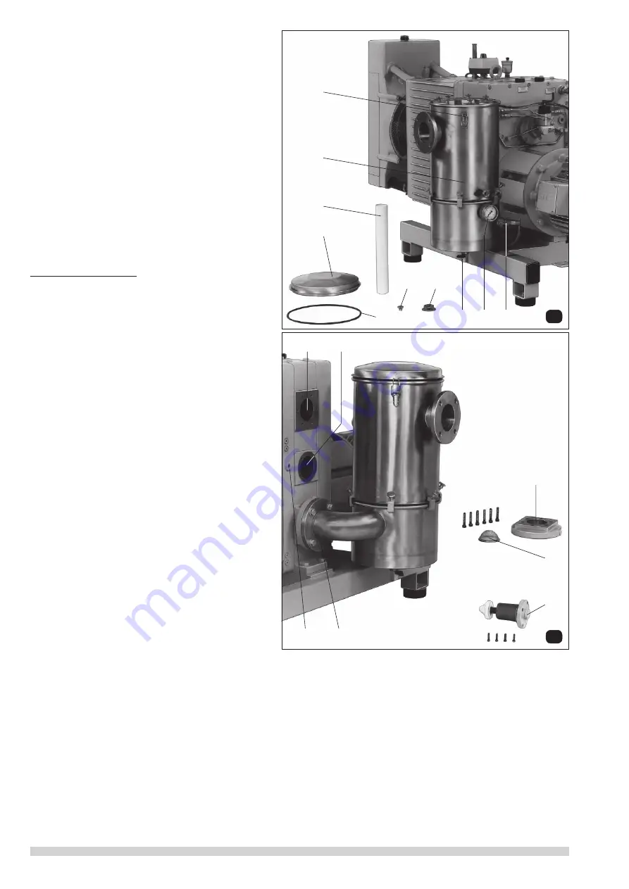
7.2.1 Oil Mist Separator Maintenance (fi g. 14)
If the backpressure on the vacuum pump as shown on the
gauge (
J
2
) rises to 0.5 to 0.6 bar then the fi lter candles (
J
1
)
should be changed and the vessel (
J
4
) cleaned out.
To change fi lter candles: after releasing the catches (
J
5
)
the oil mist separator cover (
J
6
) and o-ring (
J
7
) can be
removed. Remove the thumb wheels (
J
8
) and take off the
locating plate (
J
9
). Remove the fi lter candles (
J
1
) and before
replacing the o-ring (
J
7
) check it with particular attention.
During normal operation of the pump it is important to
ensure regular draining of the condensate and oil mixture
from the base of the separator and this can be arranged
for manual or automatic operation. A level switch (
V
7
) is
fi tted as standard and this will shut down the pump when
the exhaust condensate level becomes too high. For the
drain cock (
J
3
) as shown a solenoid valve is available for
automatic drain of oil/condensate as an optional extra.
8. Trouble Shooting
8.1 Pump Overload
1. Check oil level in gear box (only when pump is stopped),
if necessary drain down to normal.
2. Measure back pressure in exhaust lines, if necessary
change fi lter elements.
3. Check ease of rotation of gearbox and pumpstages:
➝
remove motor and turn coupling.
8.2 Drop Off of Vacuum (pict. 15)
• Measure the vacuum directly at the vacuum connection
(
A
), if necessary change mesh (
A
1
).
• Measure the back pressure on the pump exhaust (
B
1
).
It should not exceed 0.3 bar.
• If the ultimate vacuum was not achieved in the fi rst
test:
- remove protection mesh (
A
1
) behind suction fl ange (
X
1
)
and clean.
- remove inter-stage relief valve (
Q
) at (
Q
1
) and check
operation as well as position of the valve.
• Measure the vacuum between the stages using
tapping (
Q
2
). If the same reading is obtained at suction fl ange (
A
) and (
Q
2
) then the LP stage is not functioning. If the read-
ing at (
Q
2
) is closer to atmospheric pressure, then the HP stage is not functioning.
8.3 High Oil Consumption
• In case of bearing oil loss check the shaft seals between bearing and compressor stage and change (see page 14)
• High fresh oil consumption, check the non-return valves in the oil lines for correct function and replace. Disconnect oil lines
and check if they are under vacuum.


